|
|
|
|
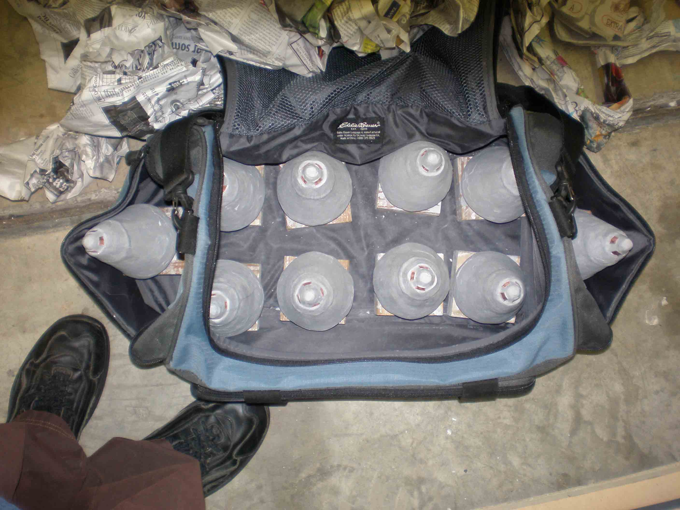
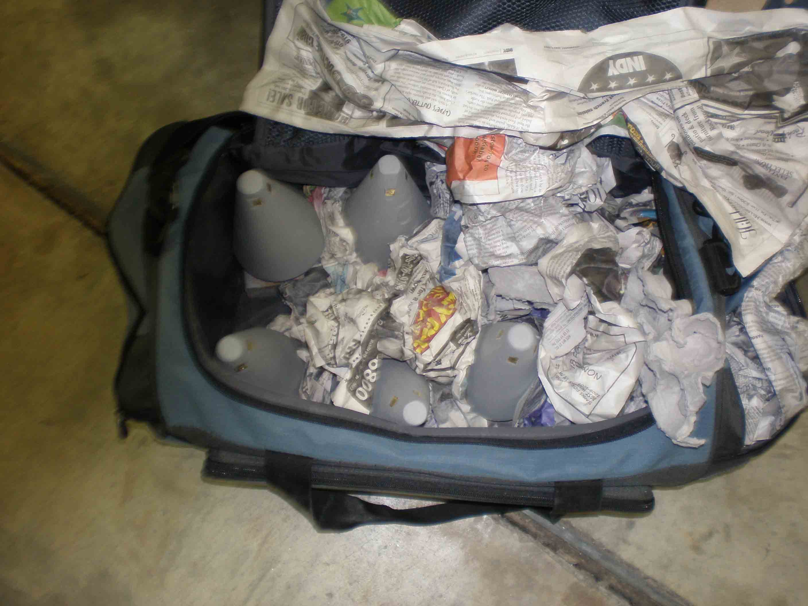
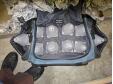
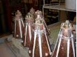
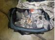
Antennas in carrying bag
Going back to NCSU for major overhaul |
|

|
|
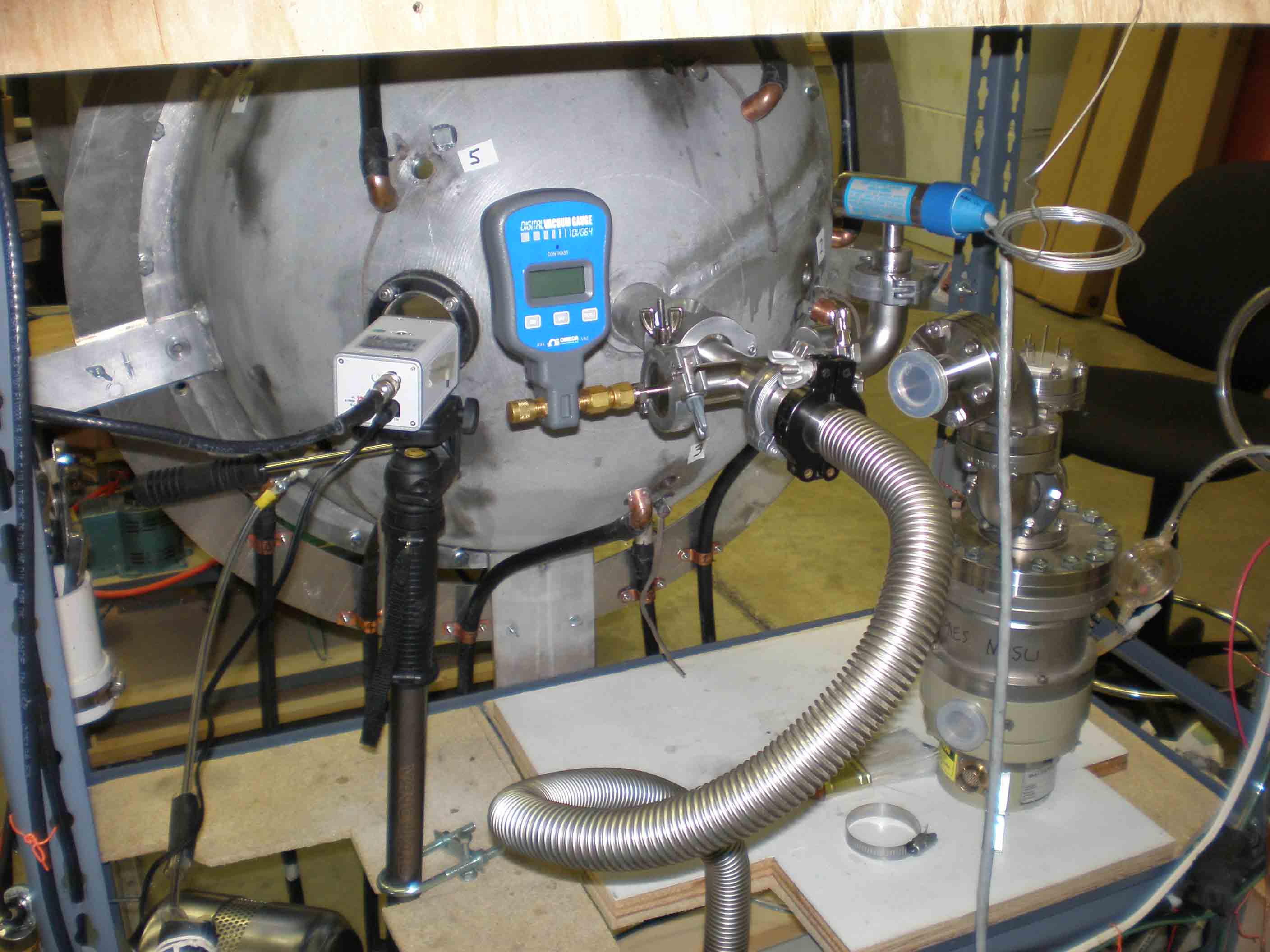
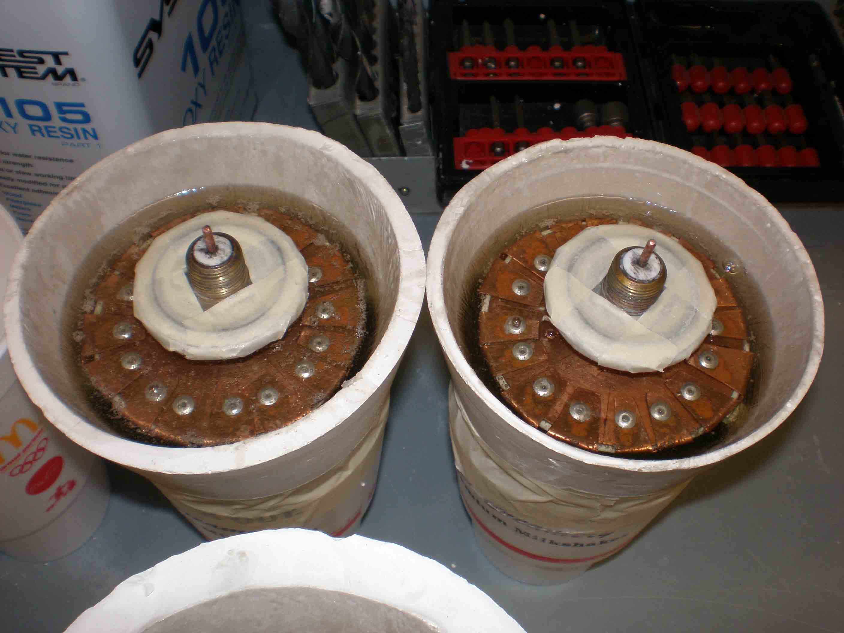
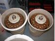
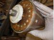
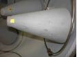
NH gear
Showing extra thermocouple pressure gauge, turbo pump |
|
|
|
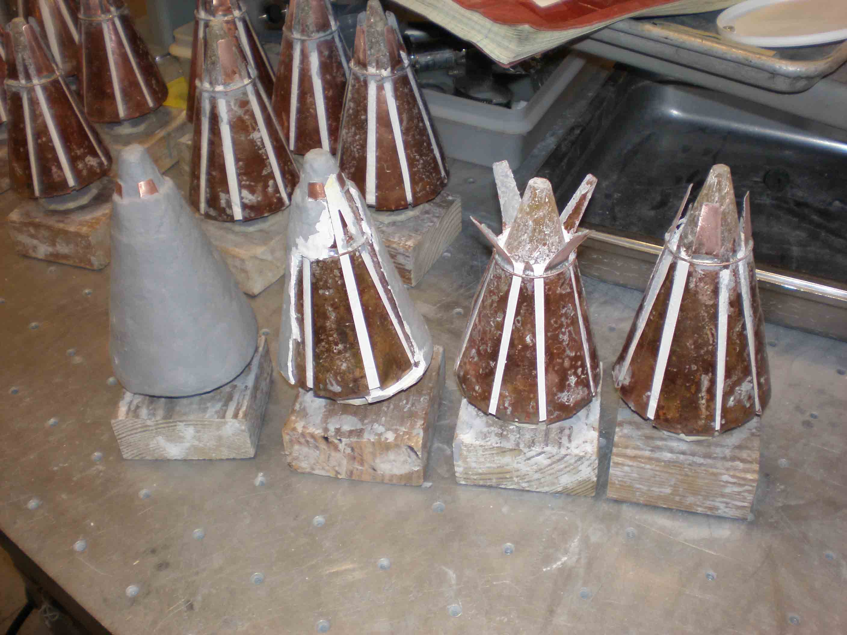
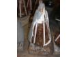
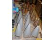
Stripping antennas
The antenna ceramic was outgassing; I took them home to NCSU, tore off the exterior and prepped for dipping in epoxy |
|
|
|
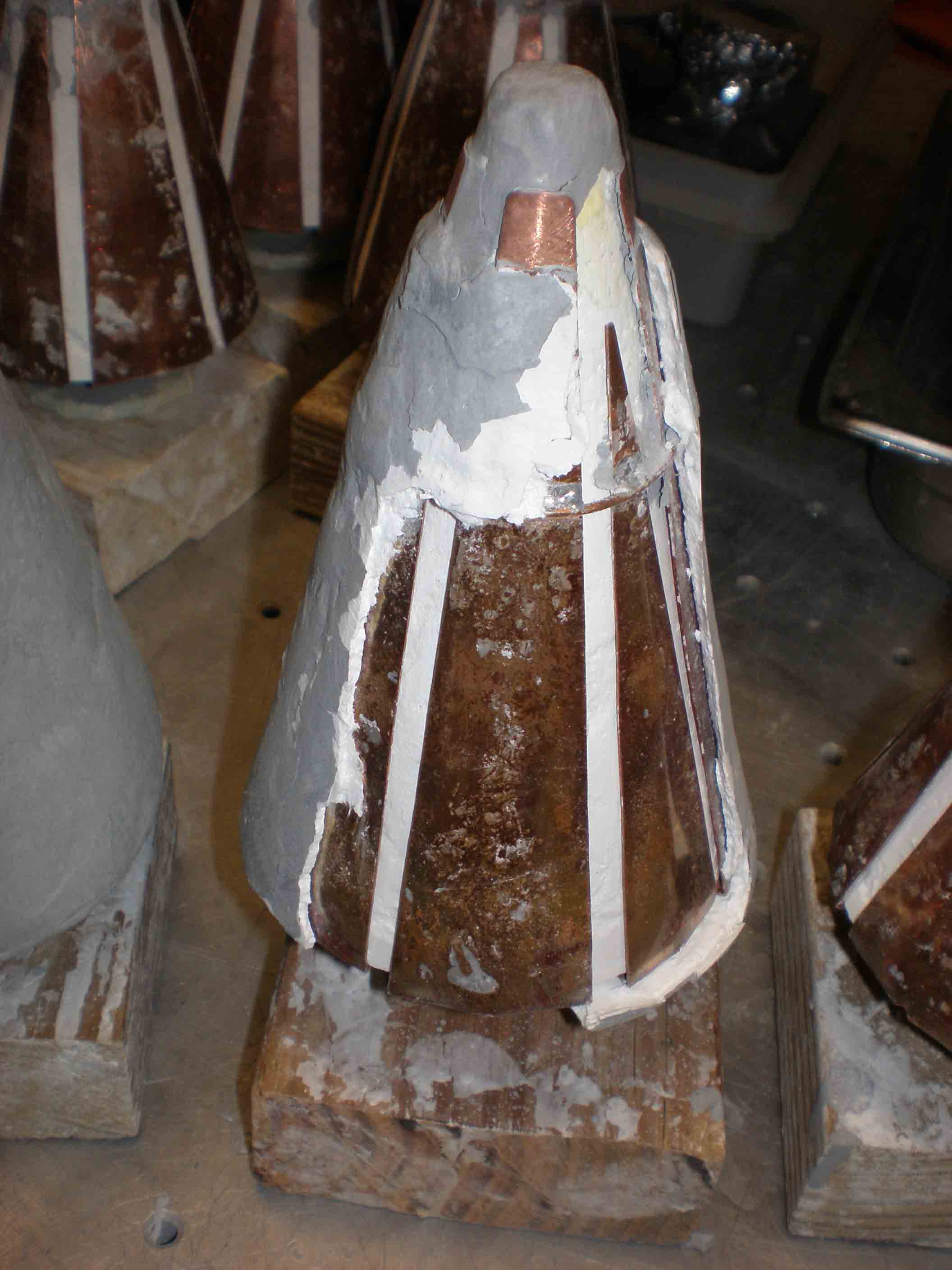
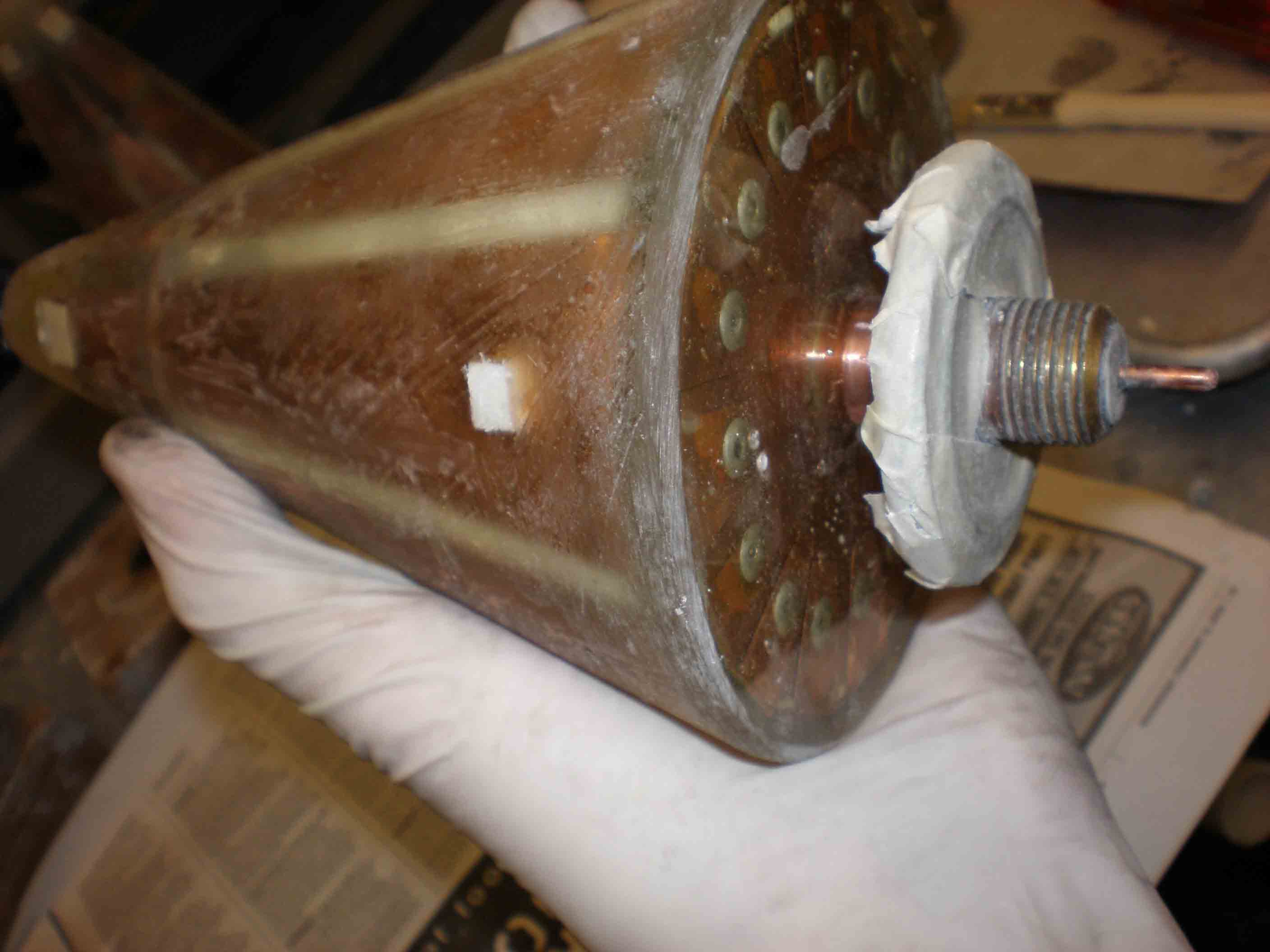
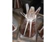
Removing ceramic
which was an expensive composite |
|
|
|
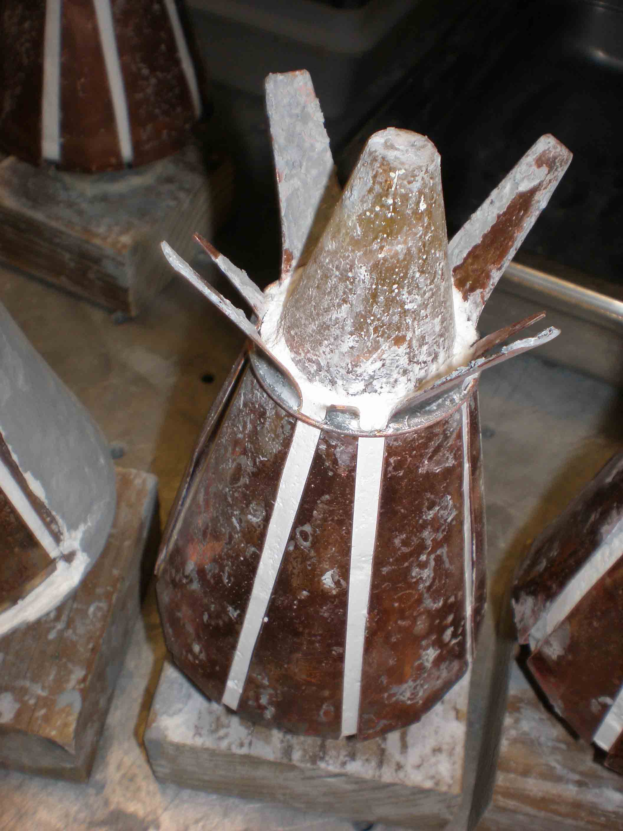
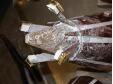
Spreading the tip
had to get under the shield at the tip |
|
|
|
|
|
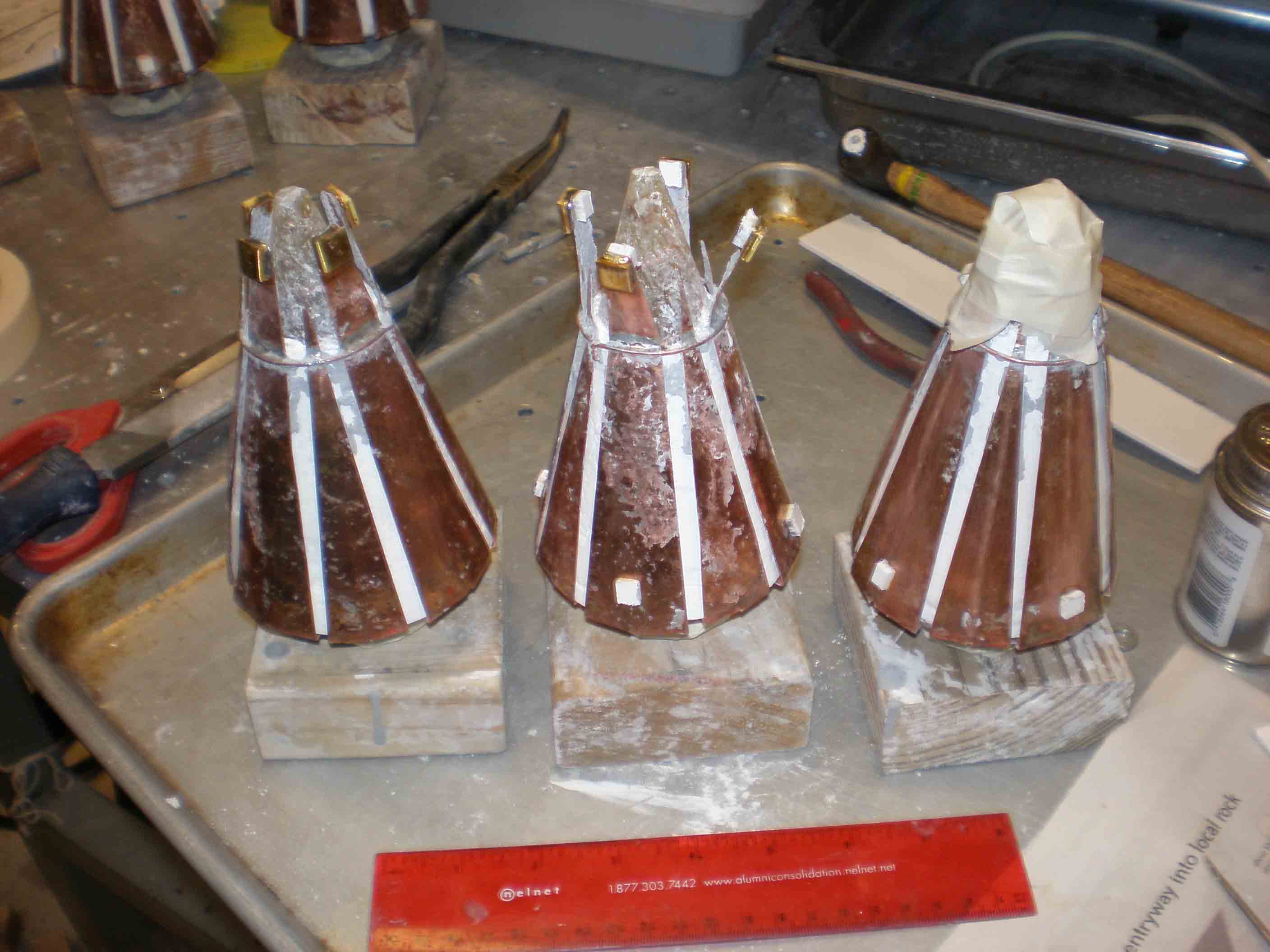
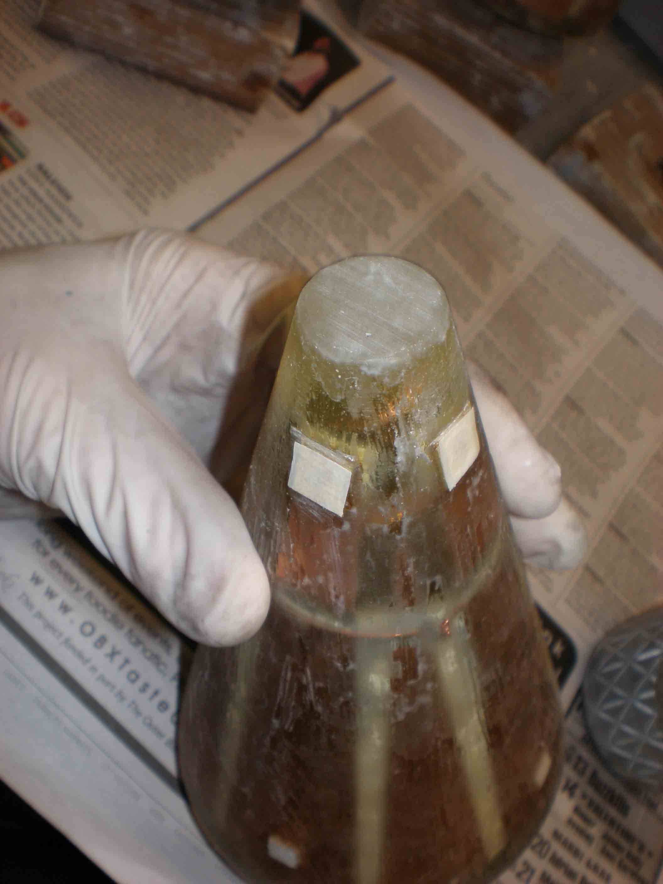
Gluing shield tips
Put in 1/8 inch PVC spacers to keep the distance correct, at the tips and also at the bases to fit the epoxy mold |
|
|
|
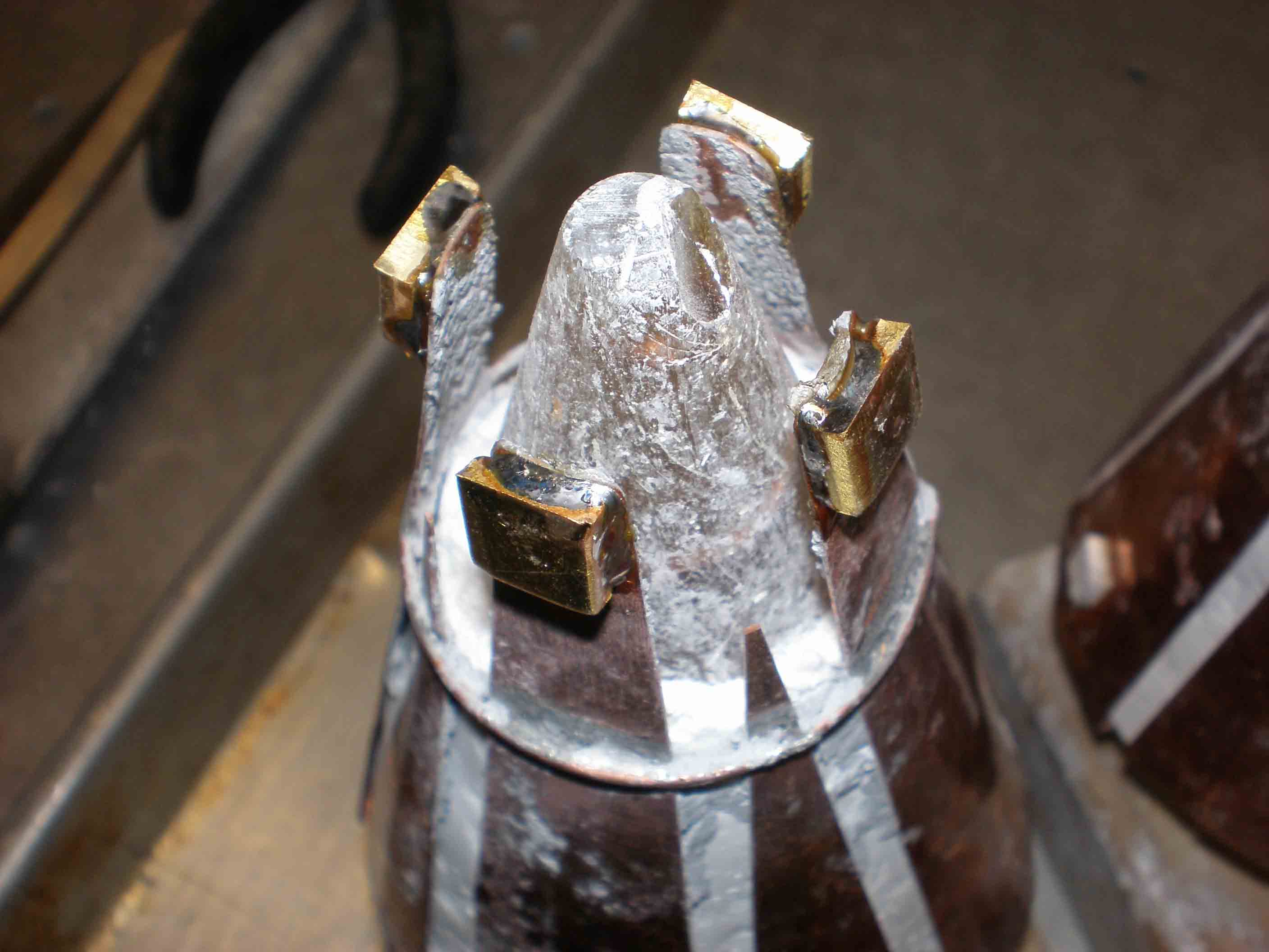
Close up PVC spacers, tip
|
|
|
|
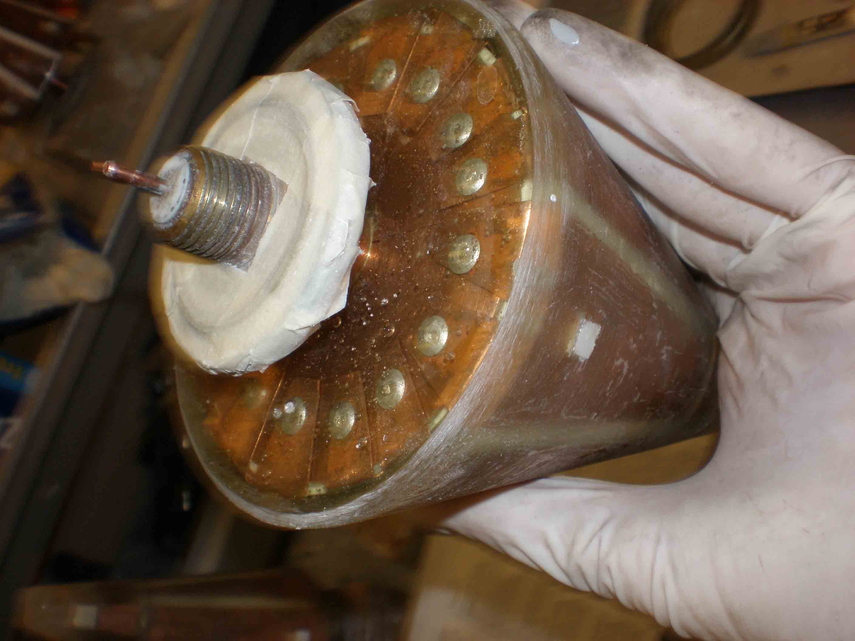
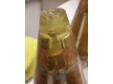
Shield tip
|
|
|
|
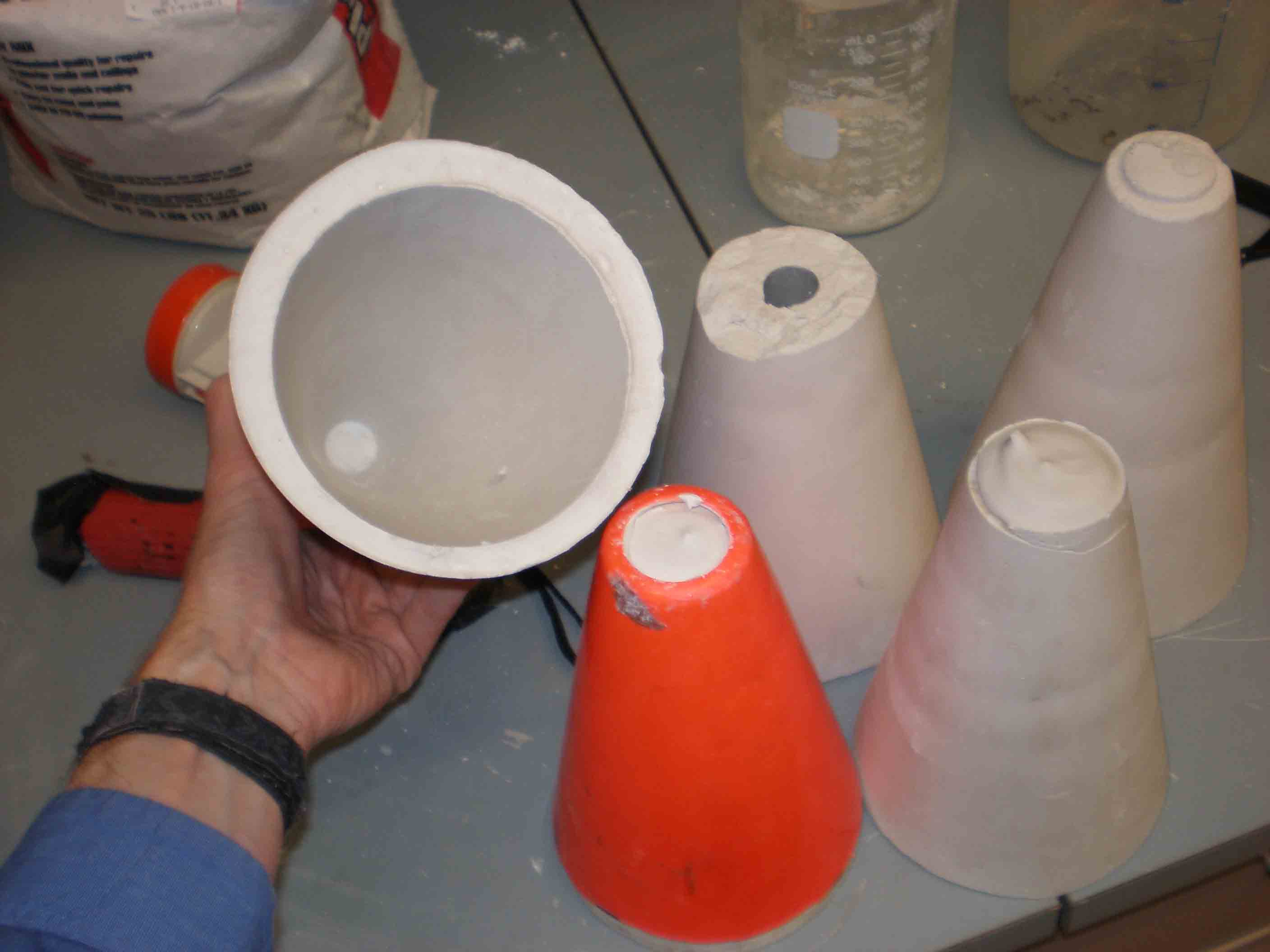
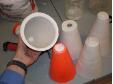
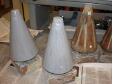
Making plaster molds
For casting the antennas into solid epoxy, I made plaster molds, liberally coatin inside with vaseline, from traffic cones |
|
|
|
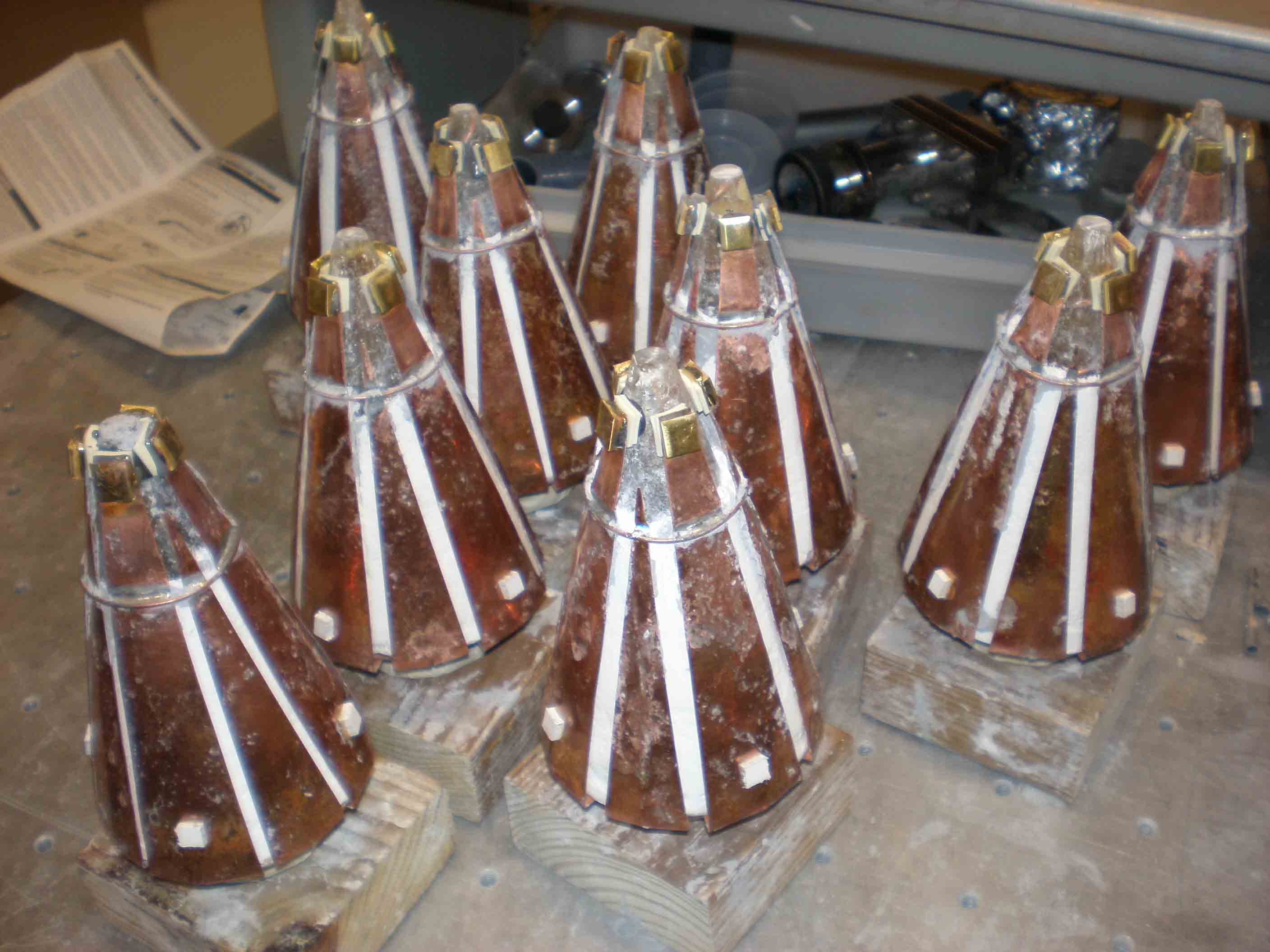
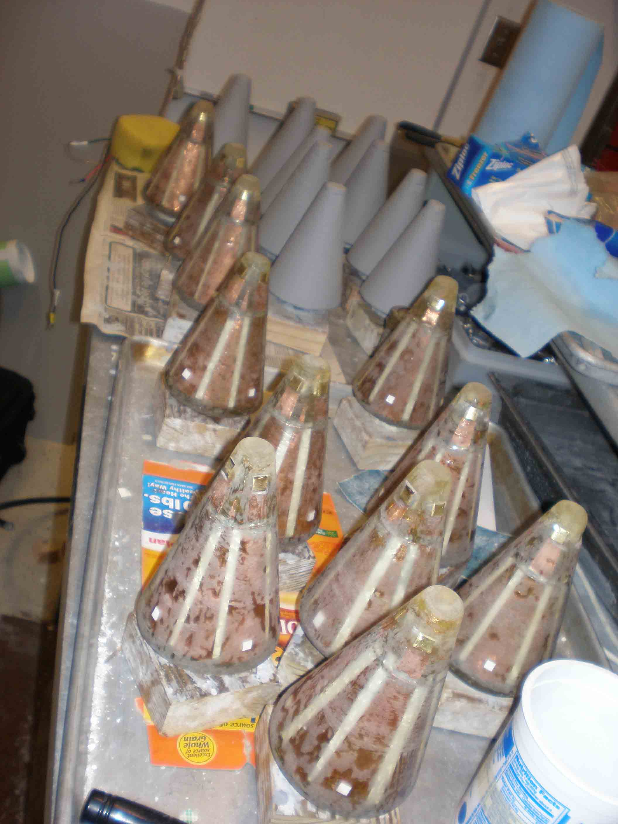
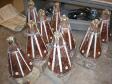
Casting antennas
Used slow cure epoxy in four pours each to keep from overheating |
|
|
|
|
|
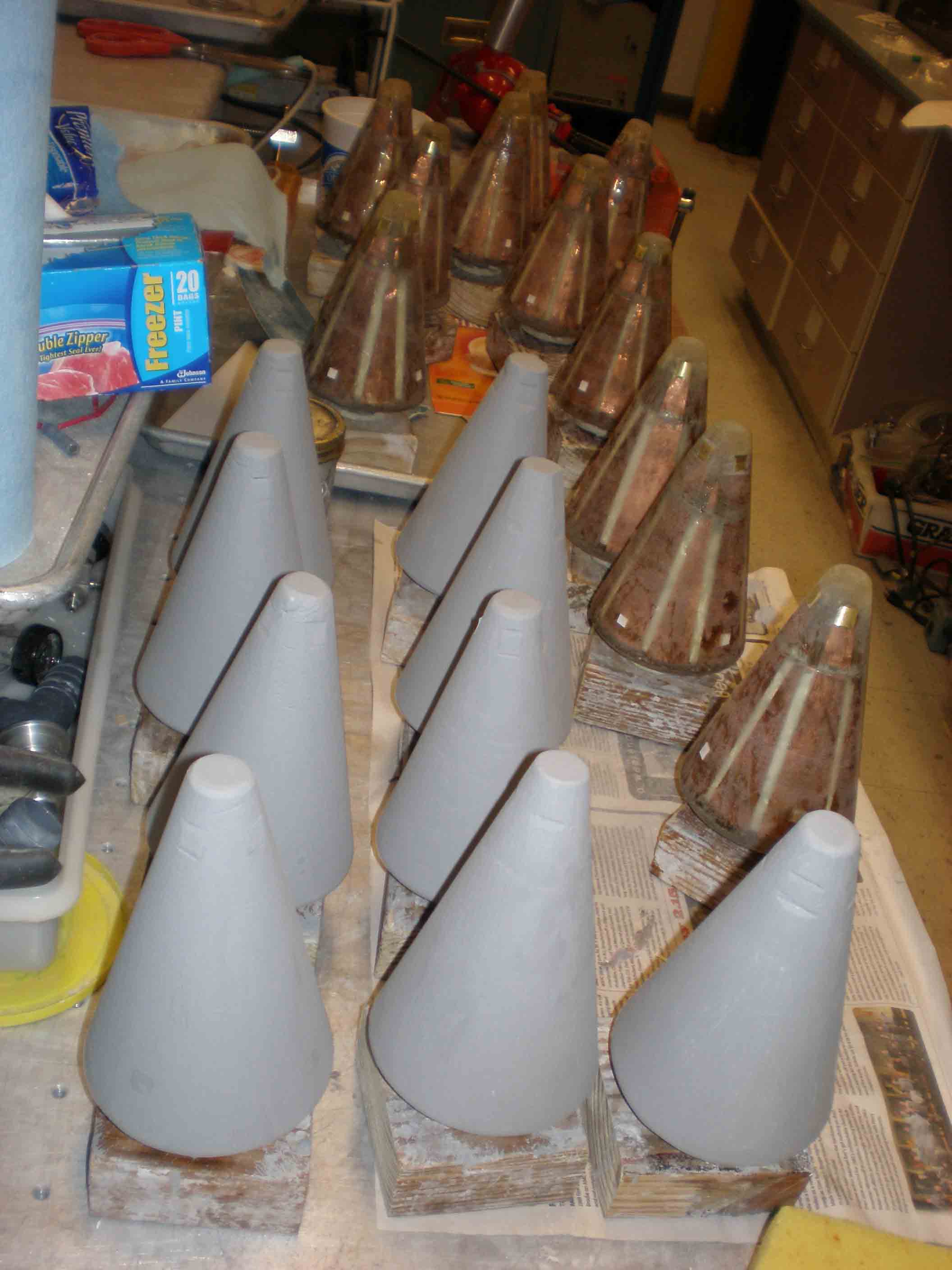
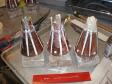
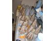
Antennas ready to cast
|
|
|
|
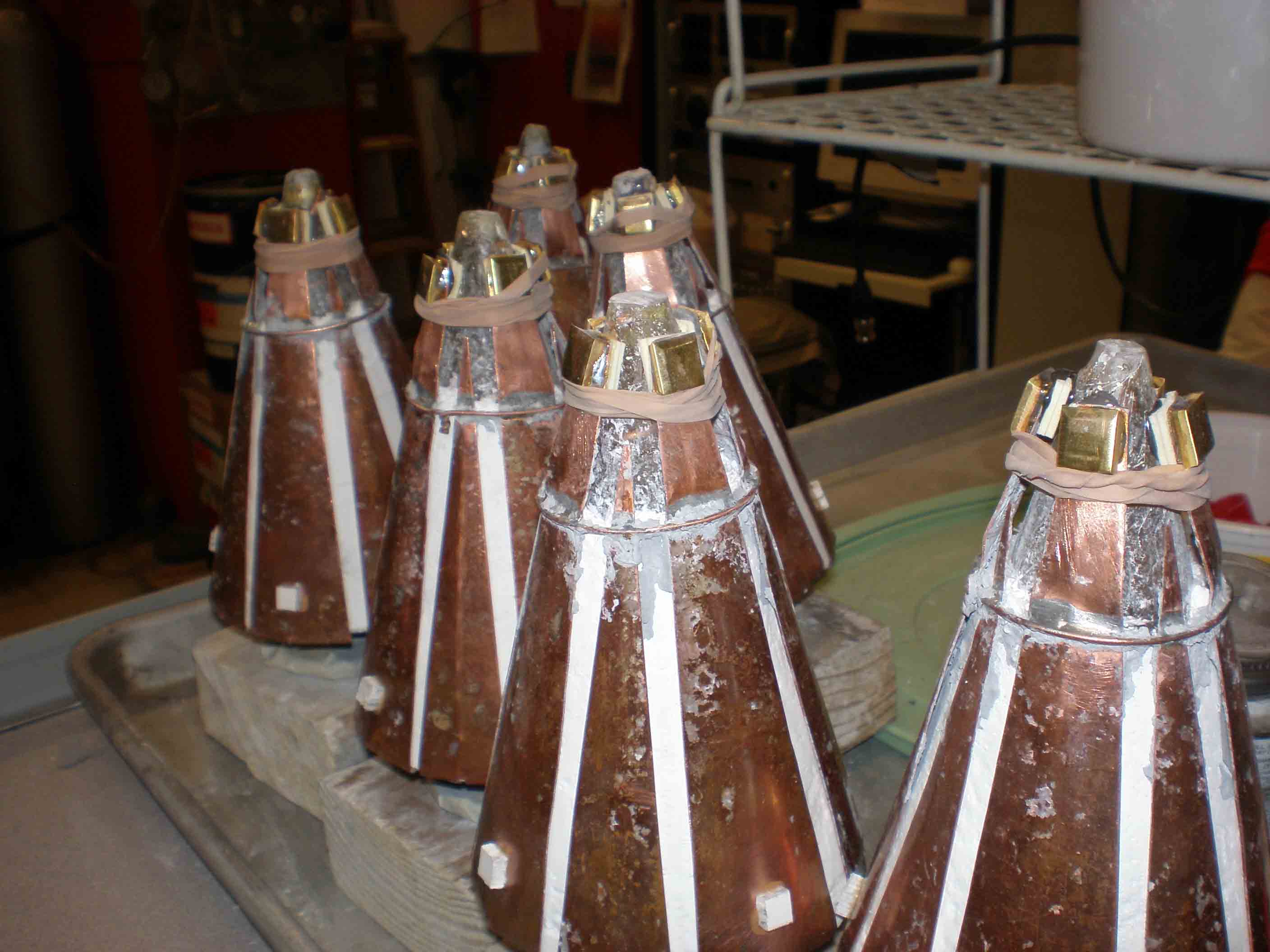
Gluing tips
had to keep them in place |
|
|
|
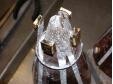
BN first coat
After pulling the antennas I gave them BN paint, which ultimately did not work well, peeling in many places |
|
|
|
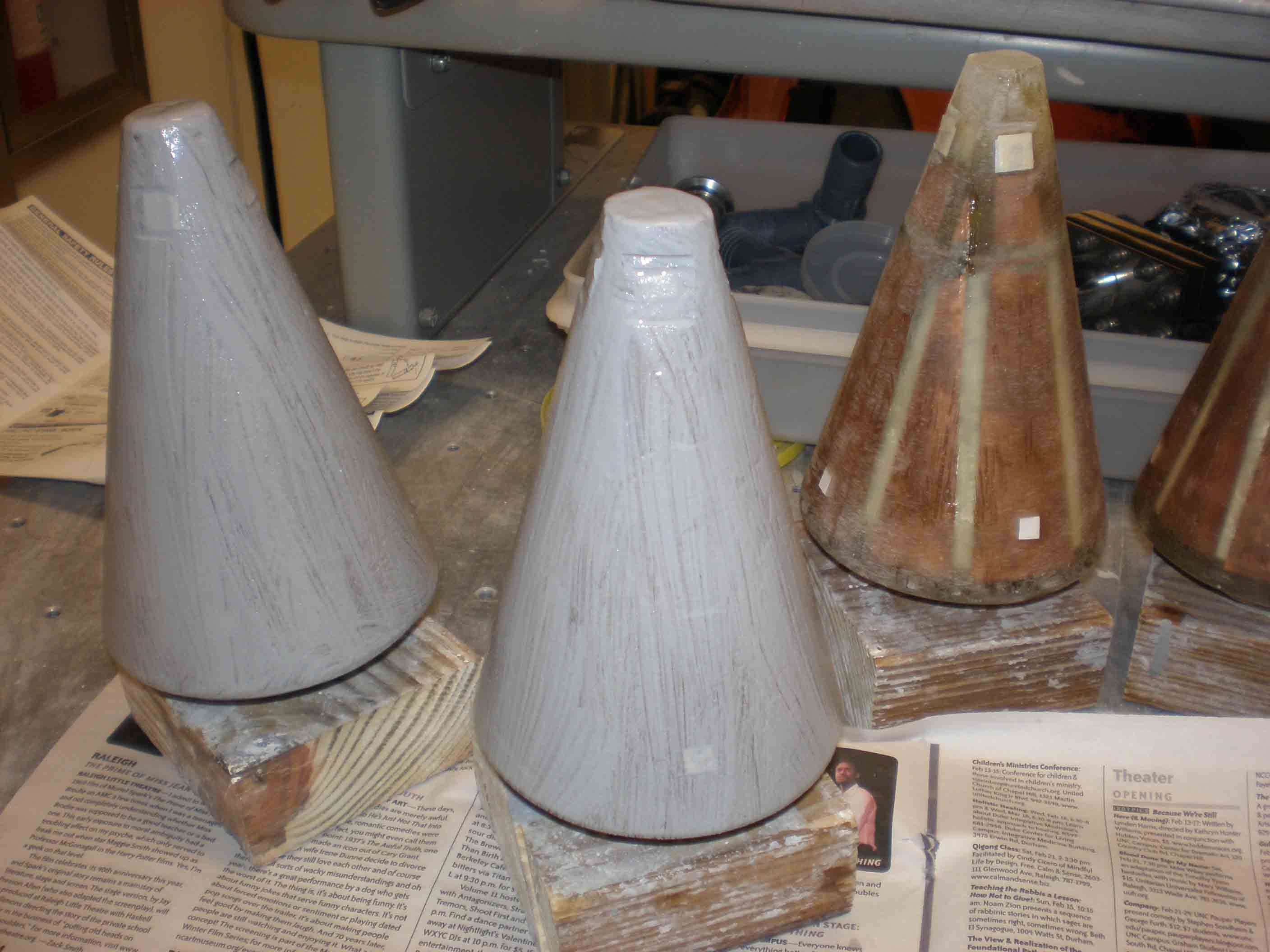
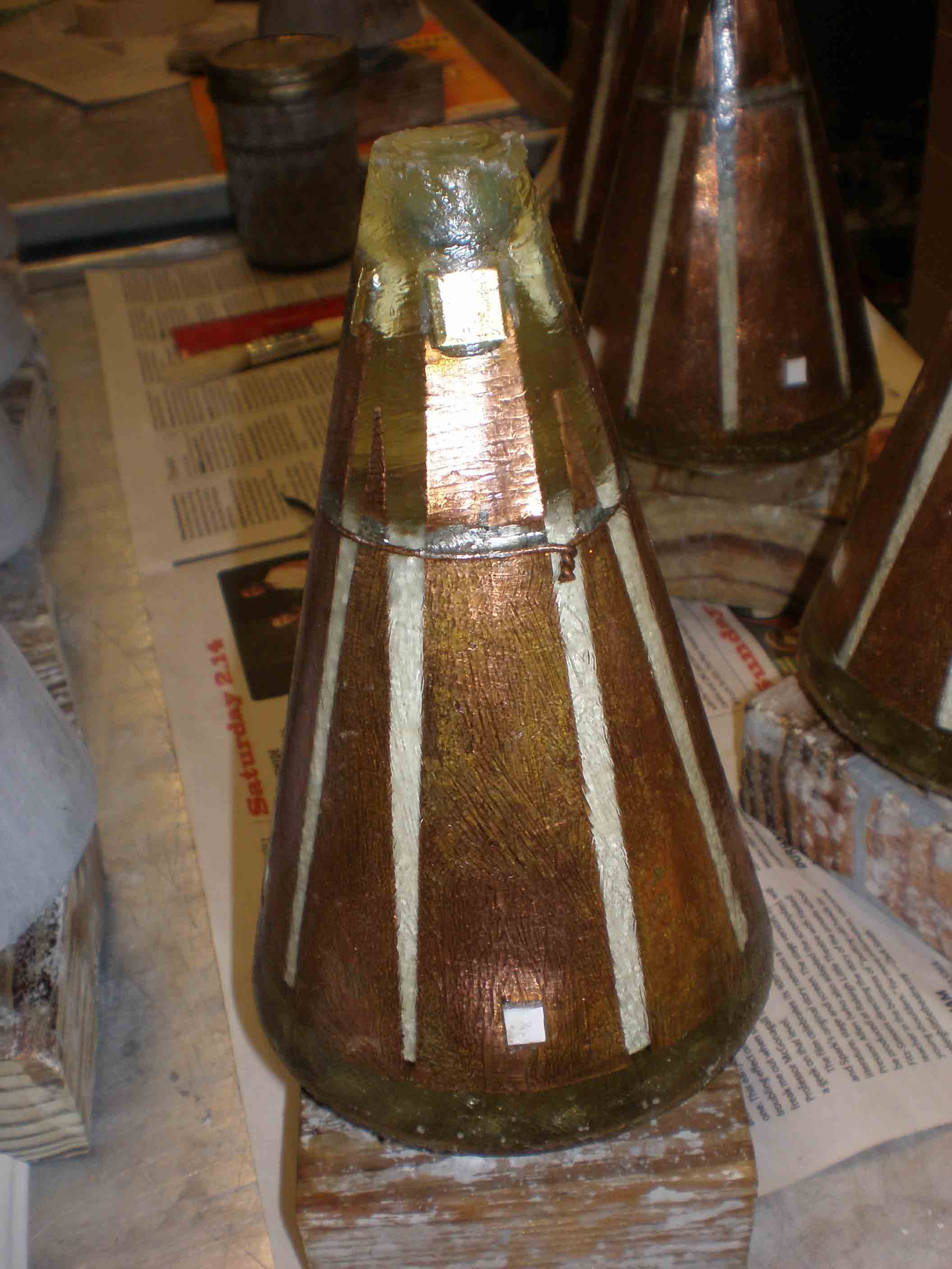
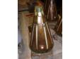
Fresh out of mold
Later antennas in an ideal future would be of low-expansion metal cast in solid ceramic and fired |
|
|
|
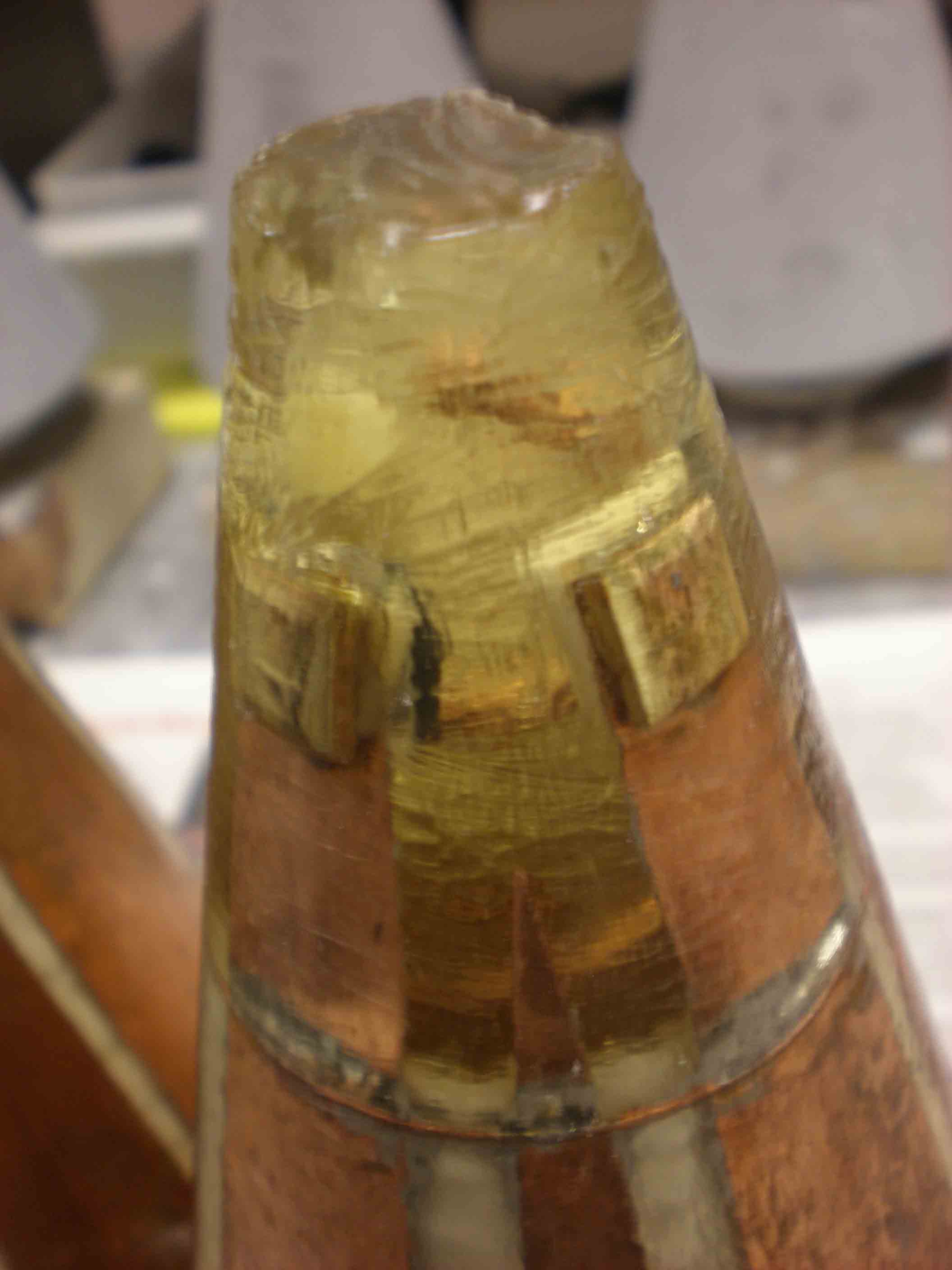
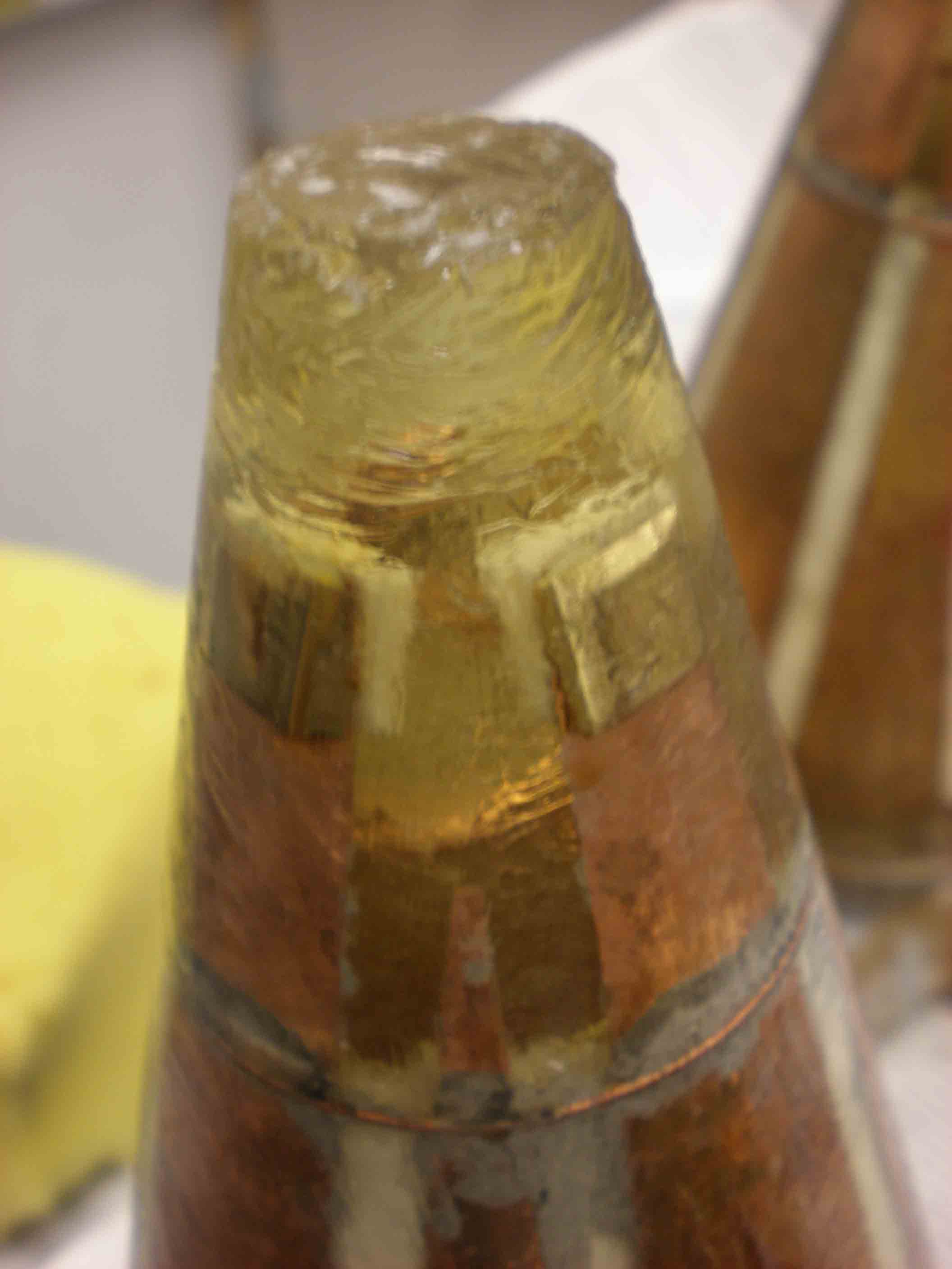
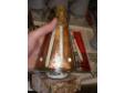
Tip of new cast antenna
you can just see the inner coil |
|
|
|
|
|
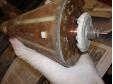
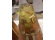
Base of cast antenna
All these pop rivets are now solidly sealed (after much bubbling) |
|
|
|
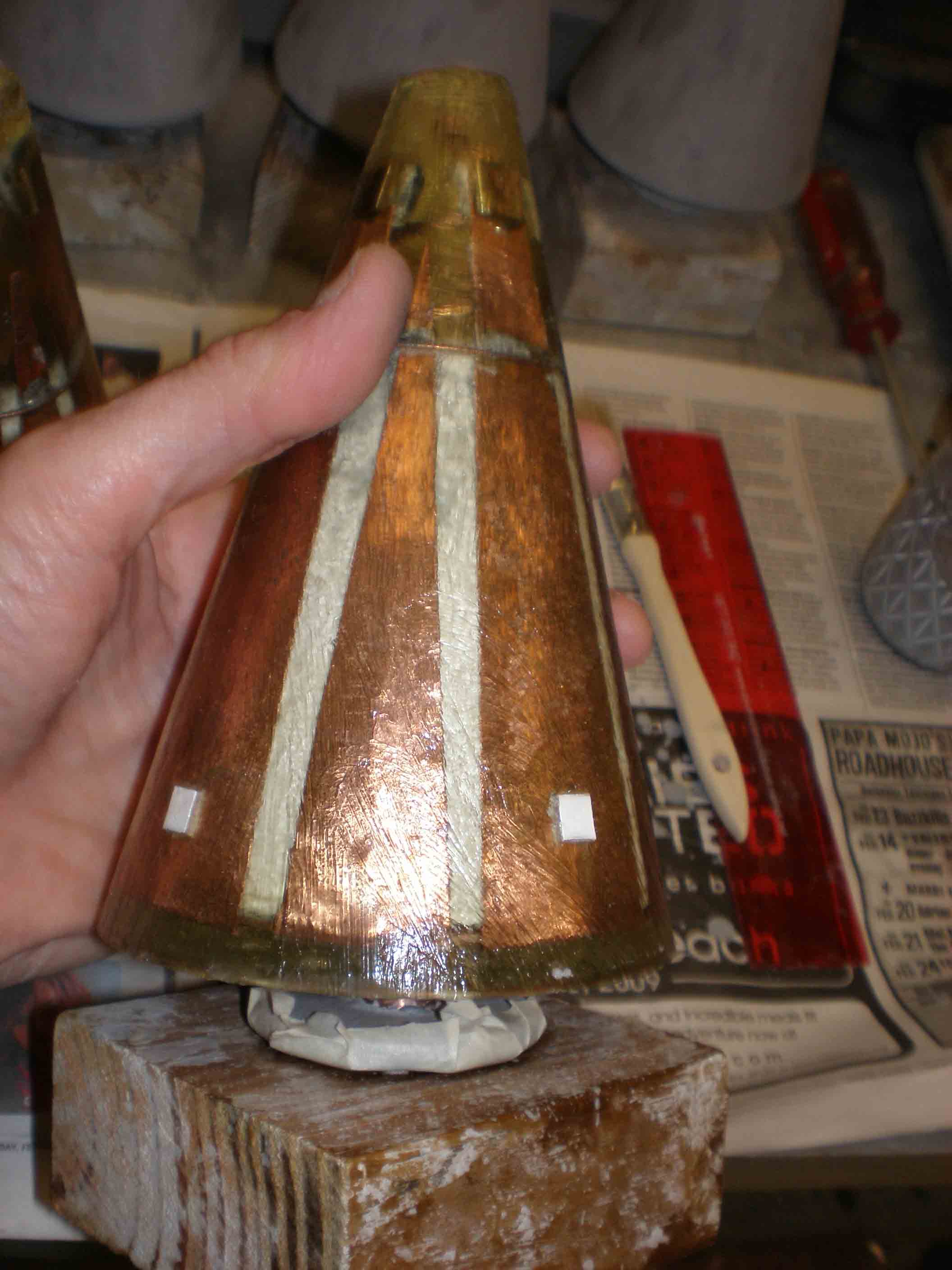
Side view cast antenna
1/8 thick coating over shields |
|
|
|
Side view cast antenna
With the Inventor's thumb |
|
|
|
Close up tip
showing inner coil, kinda cool |
|
|
|
Another close-up of tip
|
|
|
|
|
|
BN first coat
|
|
|
|
Unpainted and painted
|
|
|
|
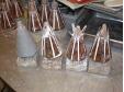
Bag painted antennas
|
|
|
|
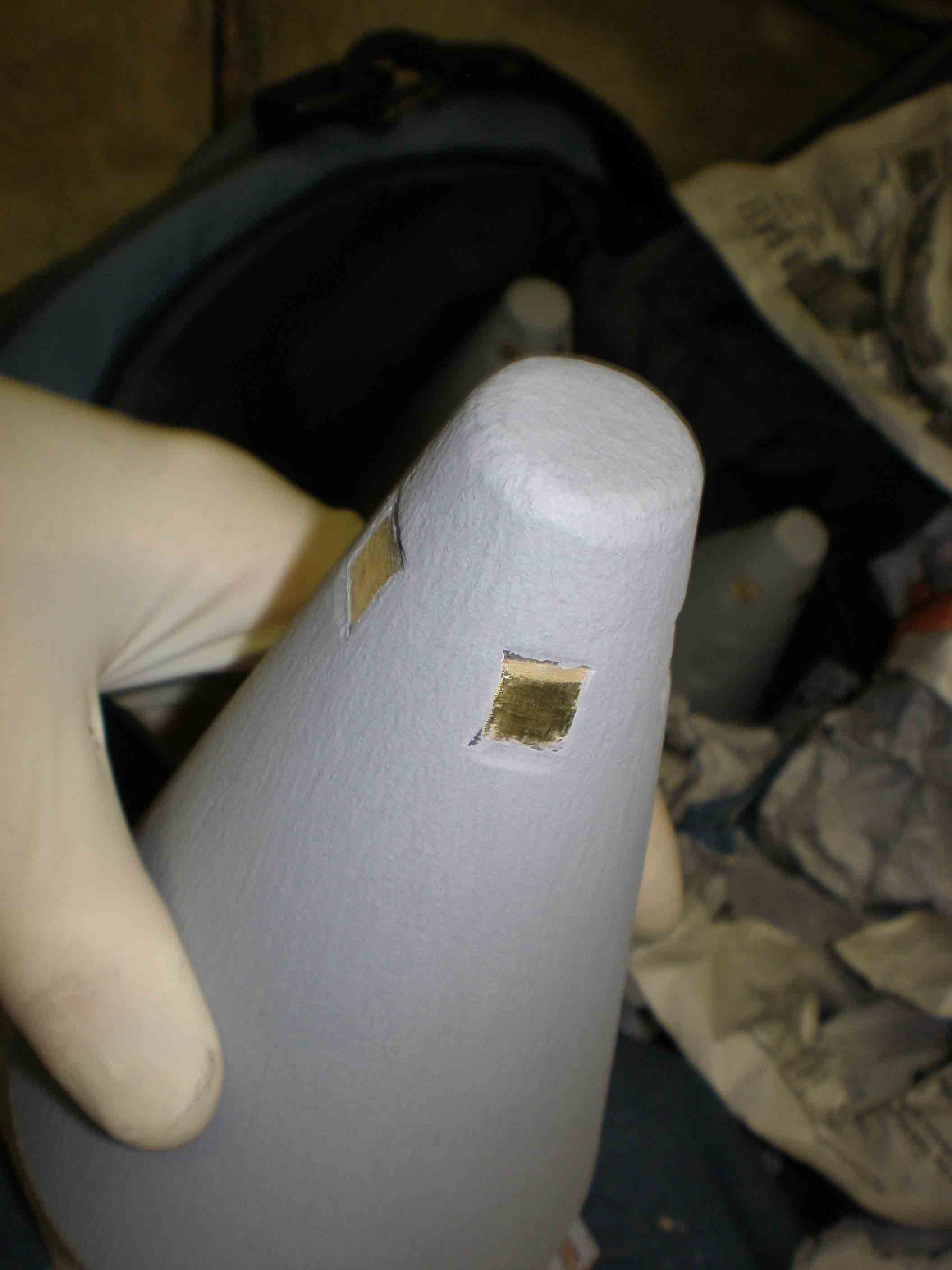
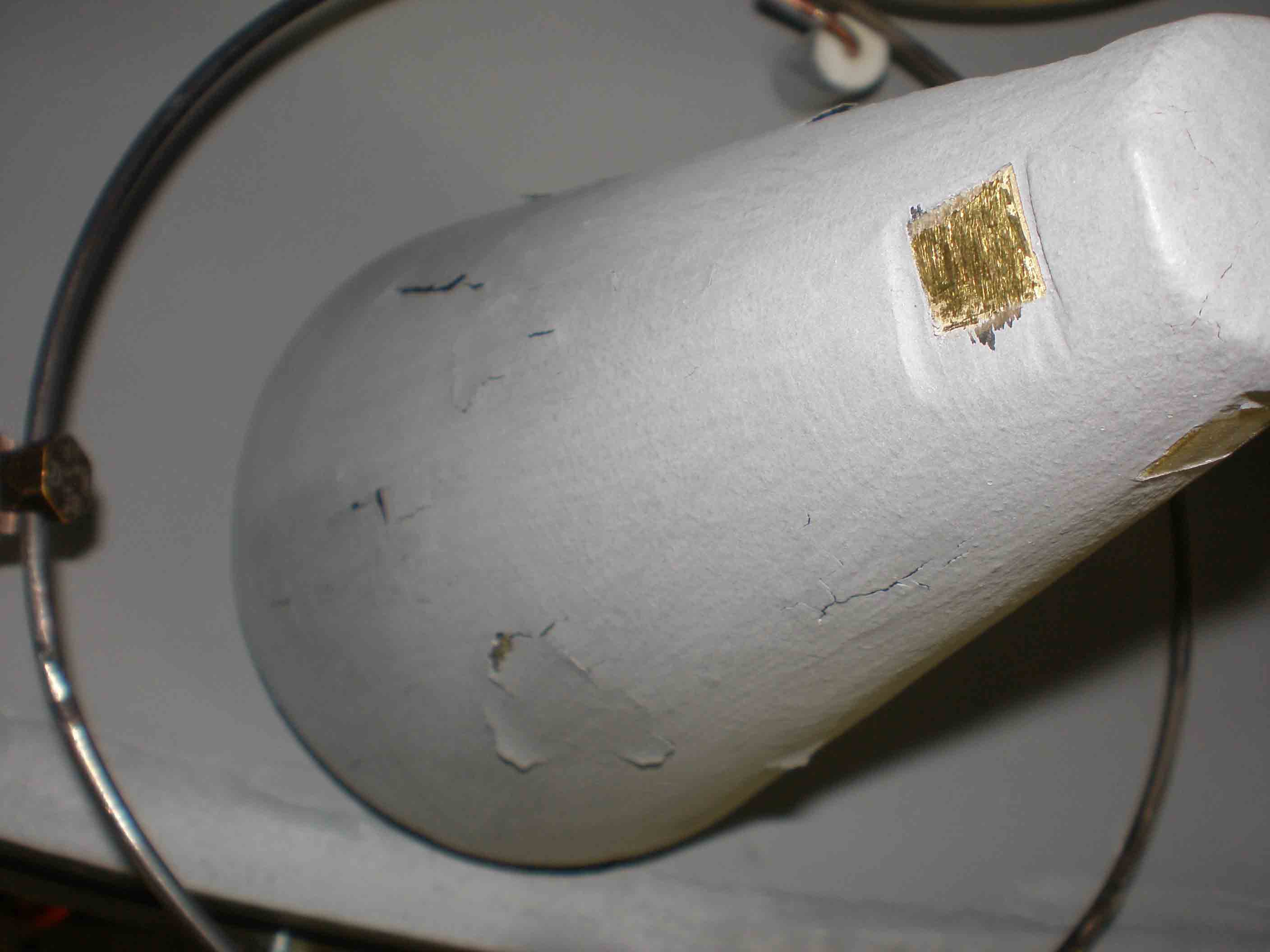
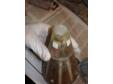
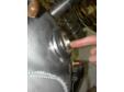
Close up painted tip
After removing BN paint from brass electrodes; need to have current from grid land here |
|
|
|
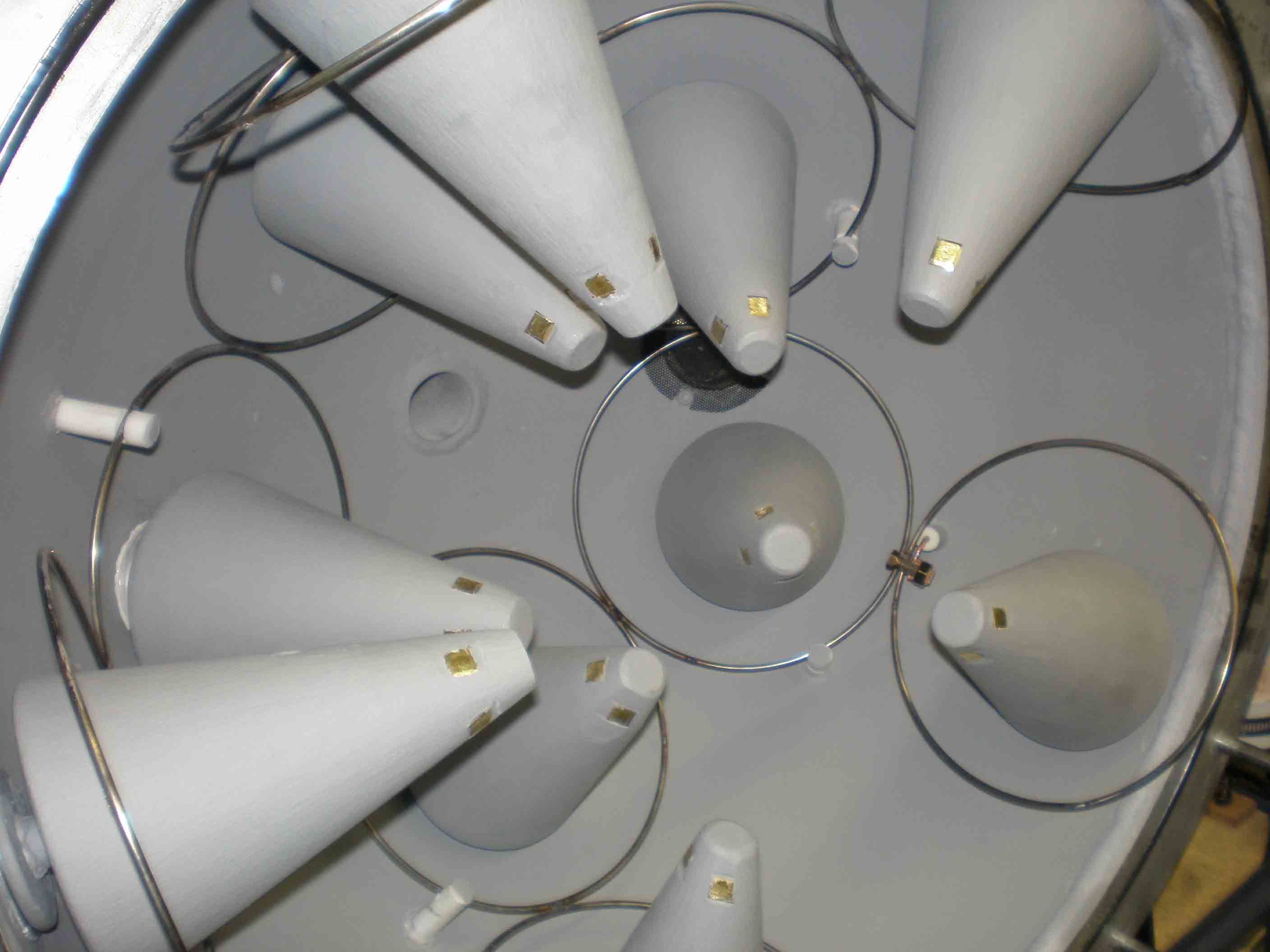
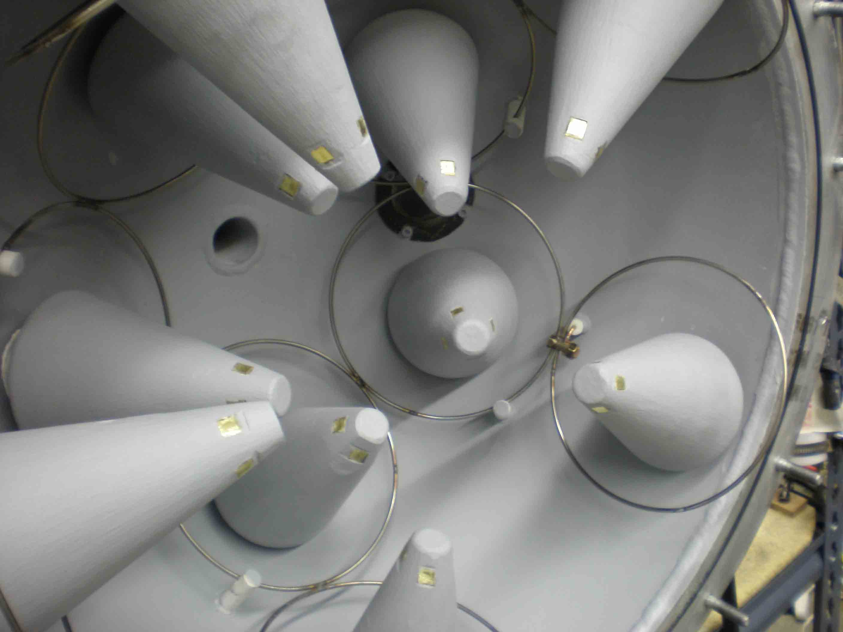
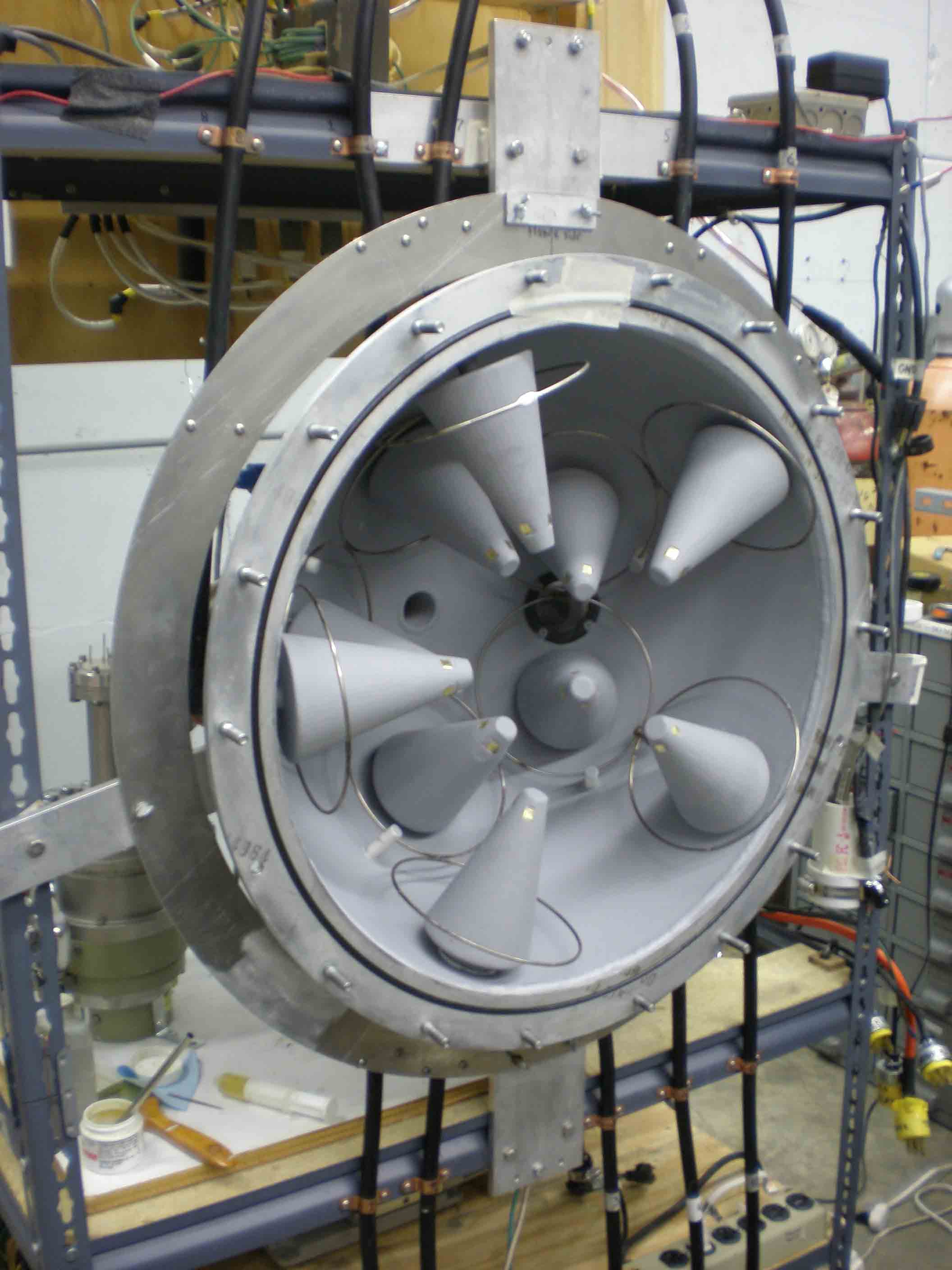
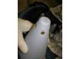
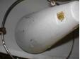
Mounted N. Hemisphere
With BN coated antennas |
|
|
|
|
|
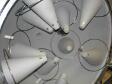
N. Hemisphere with antennas
|
|
|
|
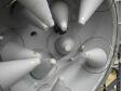
NH with antennas
|
|
|
|
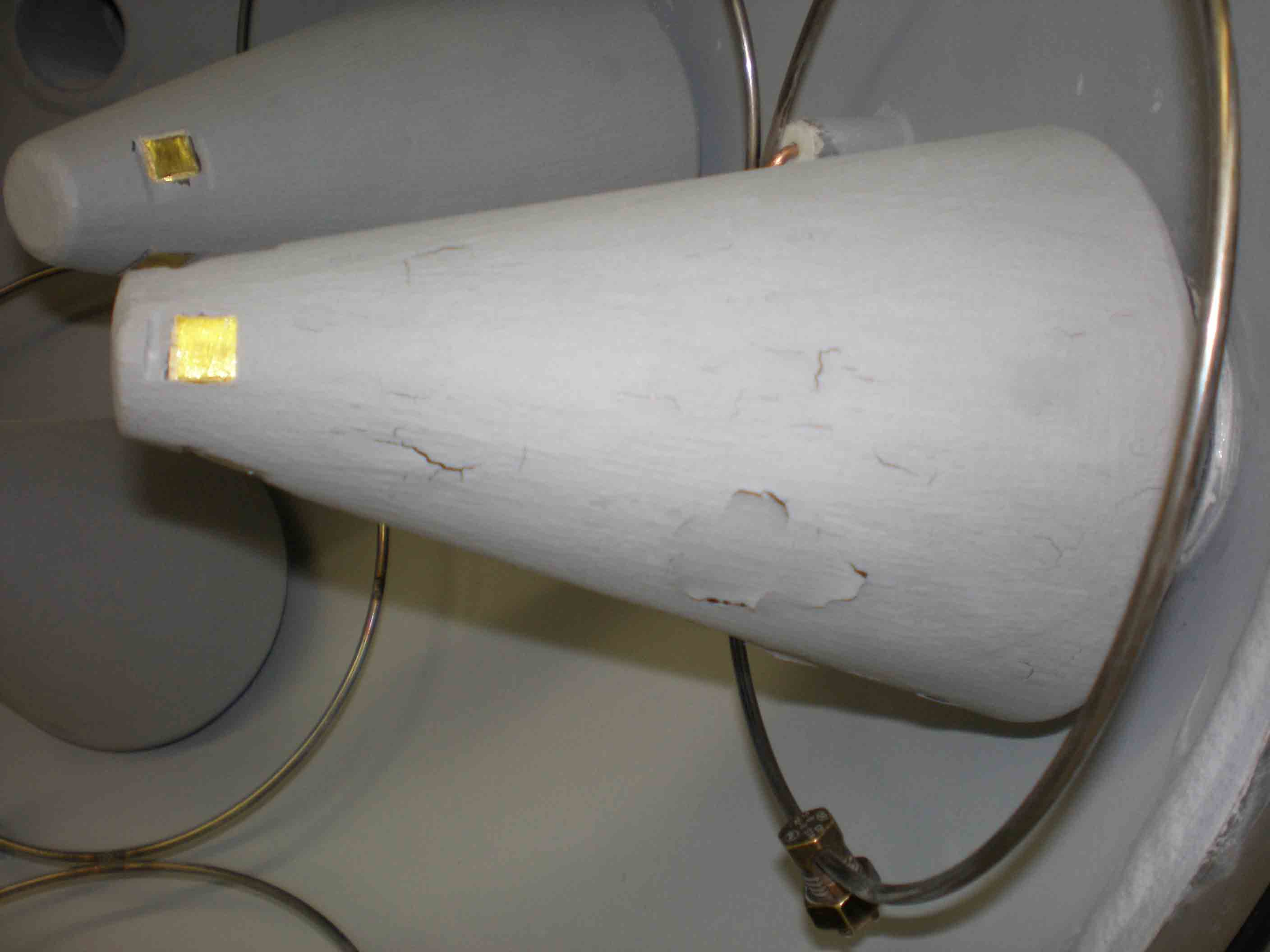
BN peeling after firing
After some use, several antennas showed peeling off the plastic |
|
|
|
Close-up peeling BN
|
|
|
|
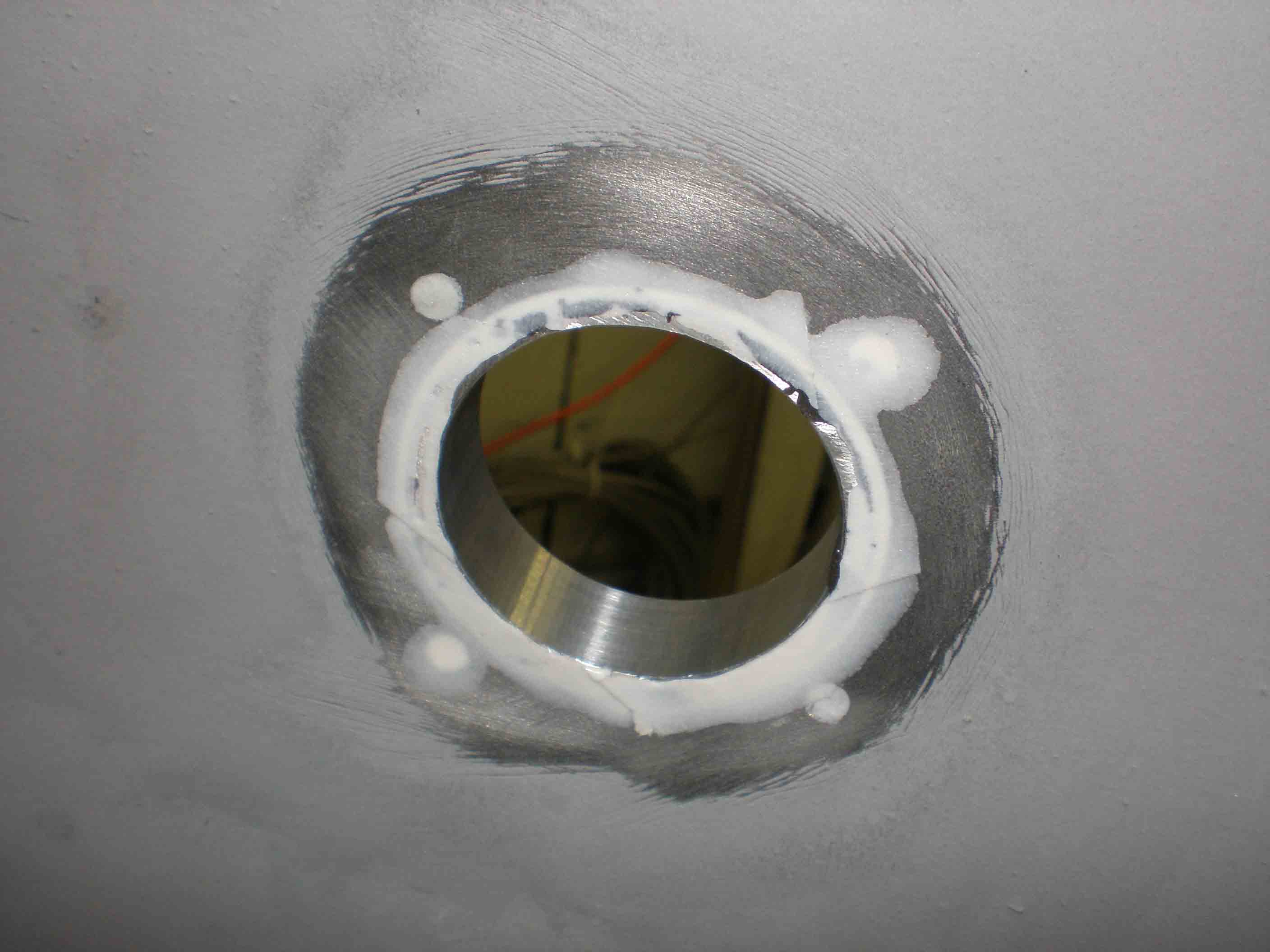
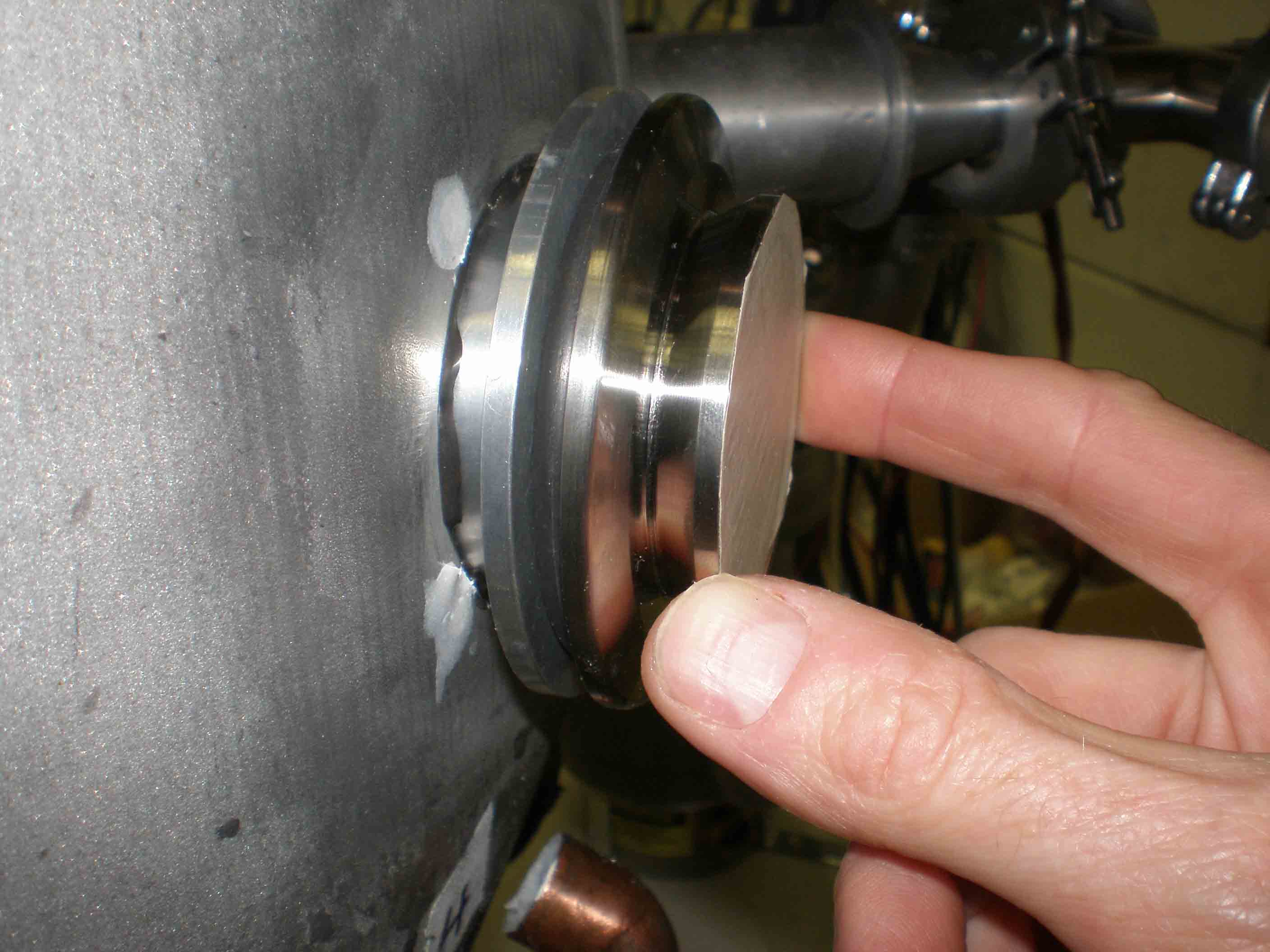
Window replacement
I had originally had home-made windows; replaced with a custom aluminum flange epoxied into the window holes |
|
|
|
|
|
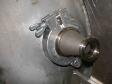
External window flange
The windows mate with KF-40 flanges as you see here |
|
|
|
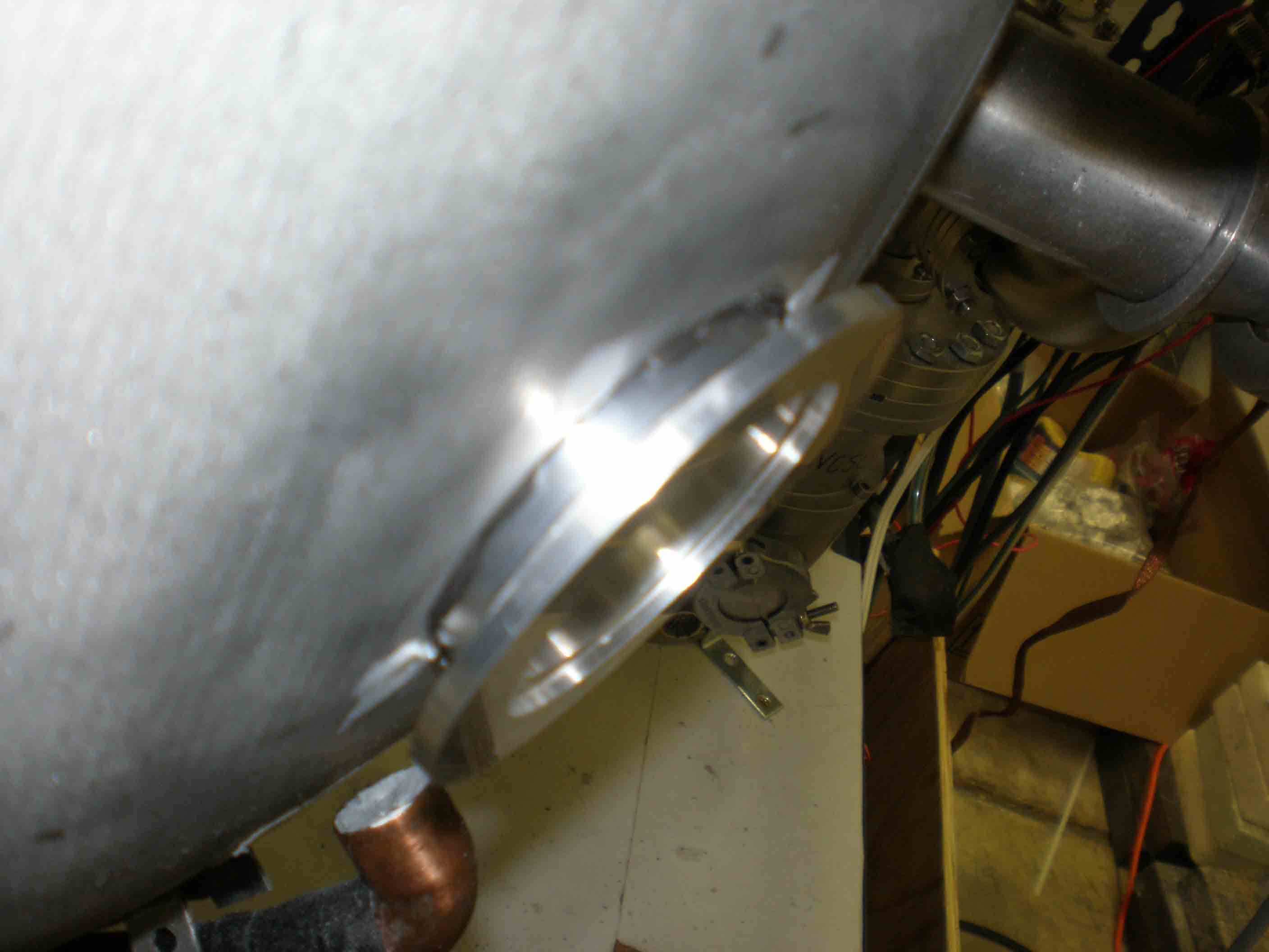
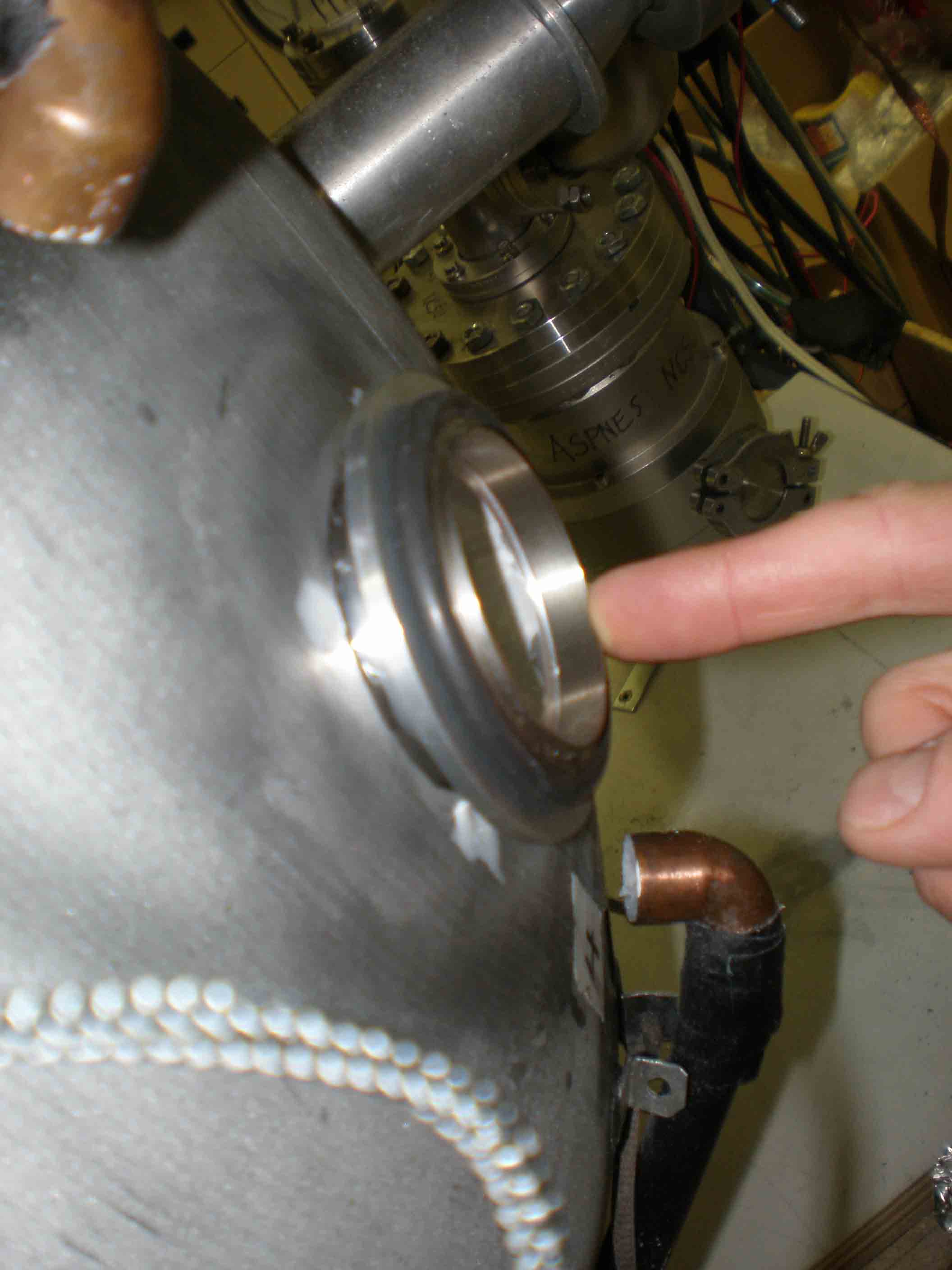
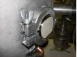
Flange on SH
One on each hemisphere |
|
|
|
Window o-ring
|
|

|
|
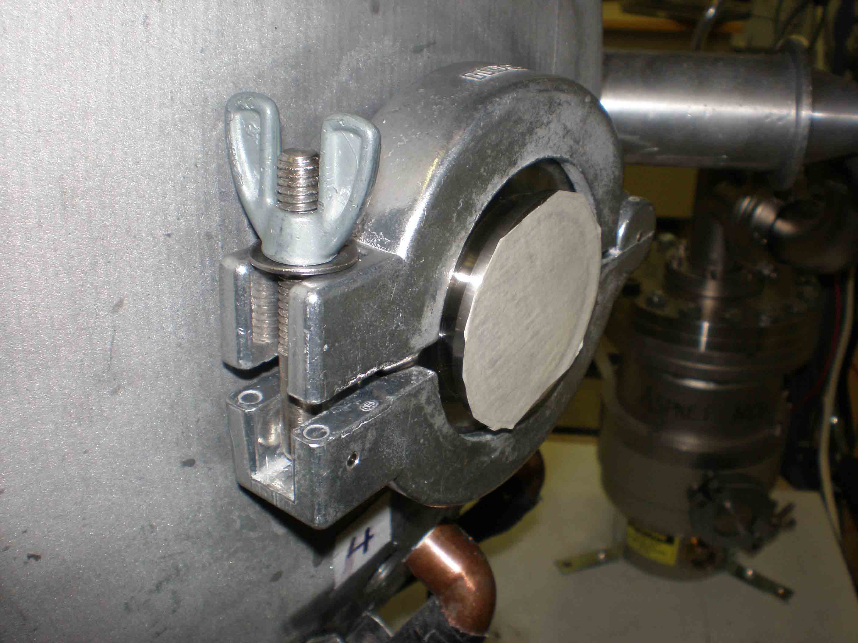
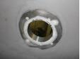
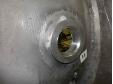
Window port NH
with protective tape over the window |
|
|
|
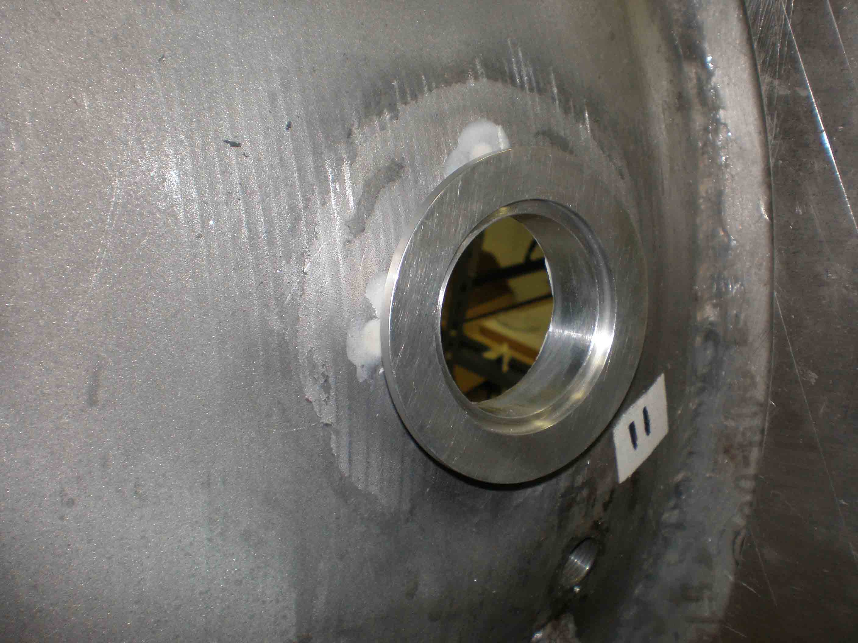
Complete window
Worked much better, allowed lower pressures; the SH leaked some but plugged with Q putty |
|
|
|
|
|
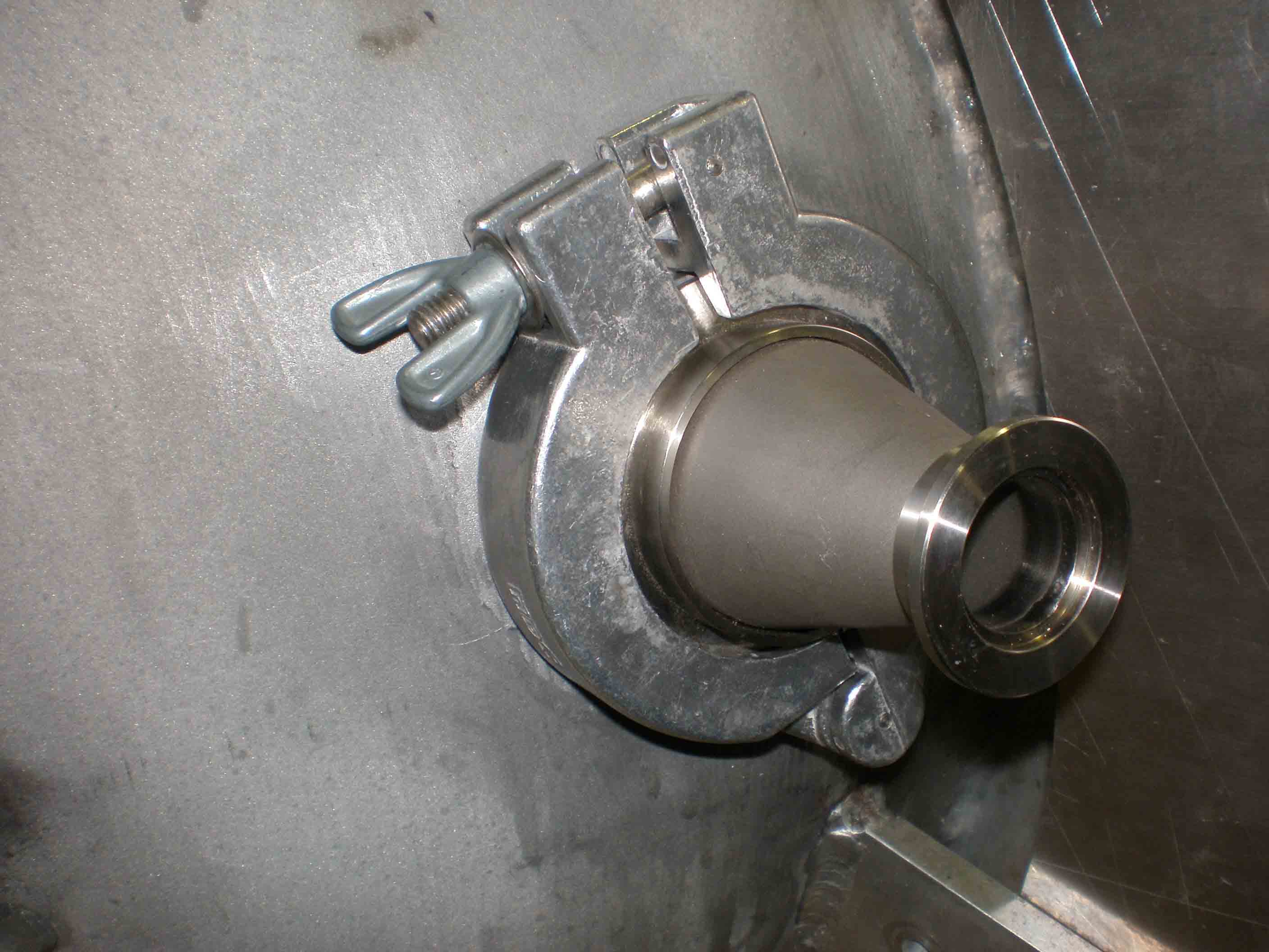
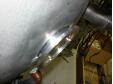
New KF25 adapter port SH
Can switch these; only bought one window ($$!) so one port is a new access, very handy |
|
|
|
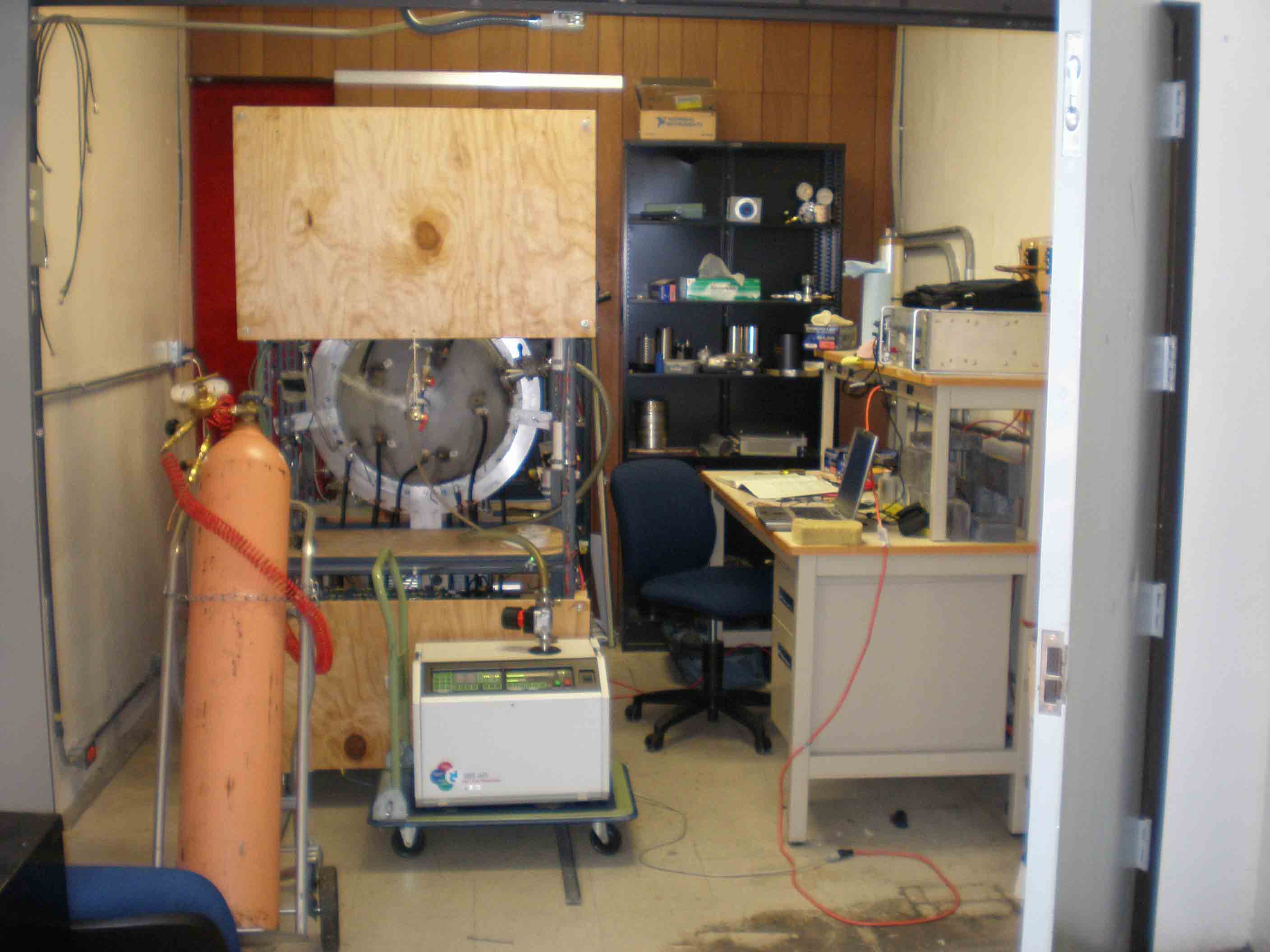
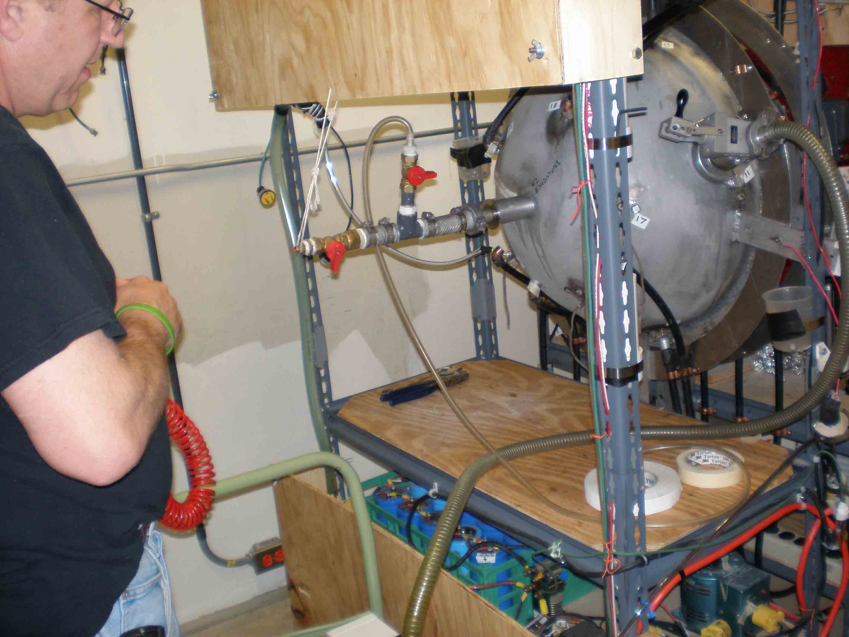
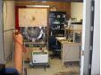
Laser room, TUNL
Put the reactor in here for leak chasing (see helium tank and white leak chaser gear) |
|

|
|
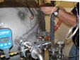
John Dunham chasing leaks
John helped a great deal during my stay at TUNL |
|
|
|
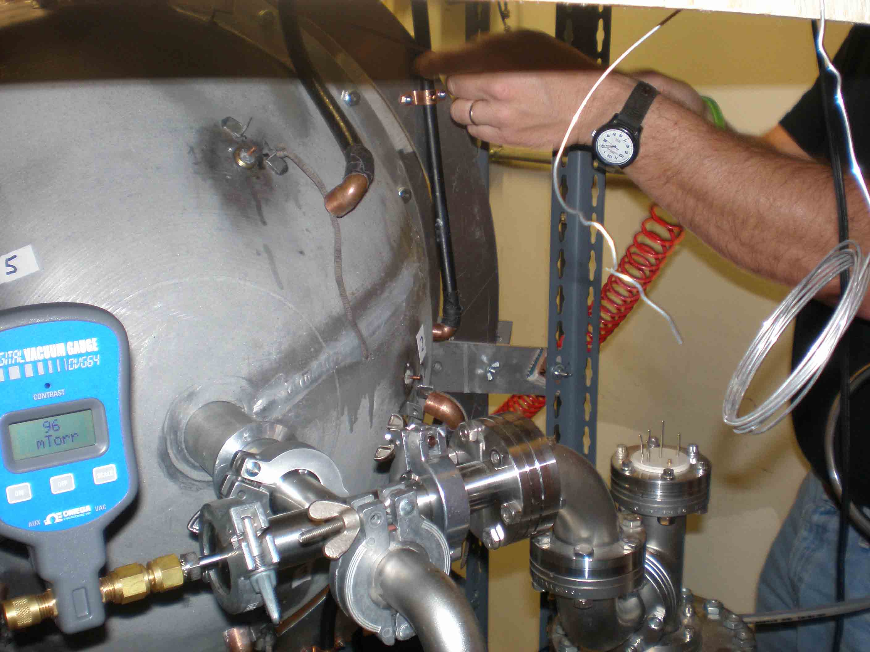
Leak chasing NH
Got down to 30 mTorr! Ten times better than before |
|
|
 Lab
Pictures 11
Lab
Pictures 11